Monostation radar target characteristic measurement method for determining region of synchronous scattering points

A radar target and scattering point technology, which is applied in the field of single-station radar target characteristic measurement and synchronous scattering point area determination, can solve the problems that cannot be eliminated and are difficult to eliminate, and achieve the effect of reducing the intensity of scattering signals and optimizing the performance of measurement darkrooms

Inactive Publication Date: 2015-04-29
BEIJING INST OF RADIO METROLOGY & MEASUREMENT
View PDF2 Cites 0 Cited by
  • Summary
  • Abstract
  • Description
  • Claims
  • Application Information

AI Technical Summary

Problems solved by technology

However, this processing method cannot eliminate the scattered signals that reach the receiving antenna at the same time as the scattered signals in the darkroom and the target to be measured. If the distances between the receiving antennas are equal, these unwanted scattered signals will also fall into the rectangular box in Figure b, and arrive at the same time as the target signal to be measured, and it will be difficult to eliminate them by the above-mentioned method of adding time-domain gates

Method used


Image

  • Monostation radar target characteristic measurement method for determining region of synchronous scattering points
  • Monostation radar target characteristic measurement method for determining region of synchronous scattering points
  • Monostation radar target characteristic measurement method for determining region of synchronous scattering points

Examples


Embodiment Construction

[0034] In order to illustrate the present invention more clearly, the present invention will be further described below in conjunction with preferred embodiments and accompanying drawings. Similar parts in the figures are denoted by the same reference numerals. Those skilled in the art should understand that the content specifically described below is illustrative rather than restrictive, and should not limit the protection scope of the present invention.

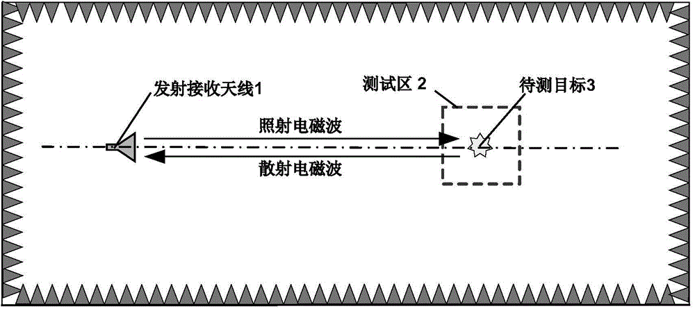
[0035] The invention discloses a method for determining a scatter point area, in particular, a method for determining a scatter point area synchronously for single-station radar target characteristic measurement, including:

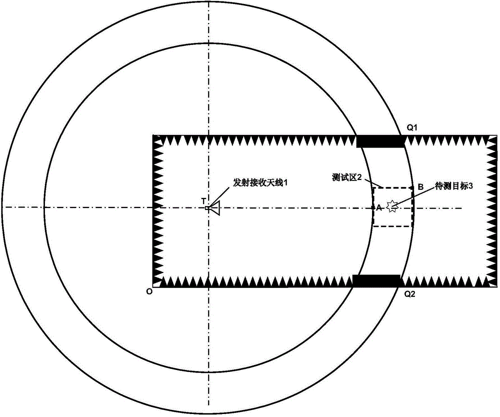
[0036] Establish a three-dimensional rectangular coordinate system in the darkroom; the three-dimensional rectangular coordinate system takes any corner of the darkroom front wall behind the transmitting and receiving antenna as the origin O of the coordinate system, takes the length direction as the X...


PUM


Abstract

The invention discloses a monostation radar target characteristic measurement method for determining a region of synchronous scattering points. The method comprises the following steps: establishing a three-dimensional rectangular coordinate system in a darkroom; determining the position where an emitting-receiving antenna is in the three-dimensional rectangular coordinate system; taking the position where an emitting-receiving antenna is as the center of a circle, taking the nearest distance and the furthest distance away from the emitting-receiving antenna in a testing region where a target to be measured is as semi-diameters respectively, and constructing two ball surfaces in the darkroom; taking the two ball surfaces and the space between the two ball surfaces as the region of synchronous scattering points through monostation radar target characteristic measurement. According to the method, the region of synchronous scattering points that signals of a target to be measured at any position of a testing region reach the emitting-receiving antenna simultaneously in the darkroom can be quickly searched; by uniformly adding wave-absorbing materials with high performance in the region or finding a solution to remove scattering sources, the scattering signal strength of the parts can be greatly reduced, and the influence of scattering of the parts on the measurement accuracy of the scattering signals of the target to be measured is reduced.

Description

technical field [0001] The invention relates to a method for determining the area of ​​a scattering point. More specifically, it relates to a method for determining the area of ​​the scatter point synchronously in the measurement of the characteristics of a monostatic radar target. Background technique [0002] With the development of stealth and anti-stealth technology, the requirements for the measurement accuracy of radar target characteristics are getting higher and higher. In order to meet the far-field conditions of classic radar target characteristic measurement, the measurement is usually carried out in a microwave anechoic chamber. Schematic diagram of indoor single-station far-field radar target characteristic measurement as shown in figure 1 As shown, the single-station measurement means that the transmitting antenna and the receiving antenna are located at the same position or are the same antenna. The distance satisfies the far-field condition, the transmitti...

Claims


Application Information

Patent Timeline
Patent Type & Authority Applications(China)
IPC IPC(8): G01S7/40
CPCG01S7/41
Inventor 马永光齐万泉王淞宇黄承祖
Owner BEIJING INST OF RADIO METROLOGY & MEASUREMENT
Why Eureka
Try Eureka