Fly-eye lenses and optical systems comprising same

A fly-eye lens and optical system technology, applied in the field of illumination devices, can solve the problems of high cost, unsatisfactory uniformity, different illumination intensity, etc., and achieve the effect of improving uniformity and intensity

Active Publication Date: 2015-04-29
SUZHOU INST OF BIOMEDICAL ENG & TECH CHINESE ACADEMY OF SCI
View PDF5 Cites 0 Cited by
  • Summary
  • Abstract
  • Description
  • Claims
  • Application Information

AI Technical Summary

Problems solved by technology

When the fly-eye lens with this structure is used in some special occasions, its illumination uniformity is much higher than that in general use occasions. In some cases, it is necessary to use two light sources and combine two sets of fly-eye lenses to perform , Figure 1-3 A schematic diagram of the illumination of the traditional fly-eye lens is given, which can obtain uniform light illumination on the illuminated surface. If two or more sets of perfunctory lens optical systems are required to be used together to increase the light intensity of the target surface, each fly-eye lens system Inclined setting is required, and the schematic diagram shows the situation where two sets of optical systems are used together. For each light source system, the optical path difference of light at different positions in the beam overlapping area is dif

Method used


Image

  • Fly-eye lenses and optical systems comprising same
  • Fly-eye lenses and optical systems comprising same
  • Fly-eye lenses and optical systems comprising same

Examples


Embodiment Construction

[0043] Preferred embodiments of the present invention will be described in detail below in conjunction with the accompanying drawings.

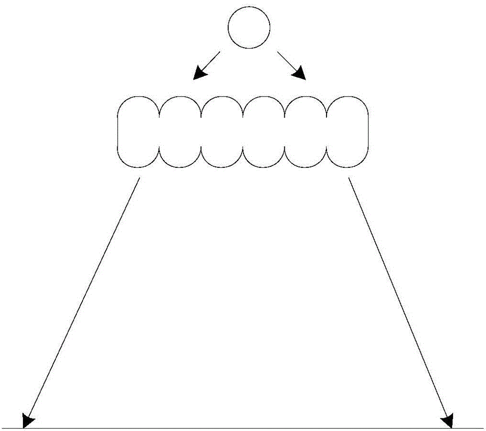
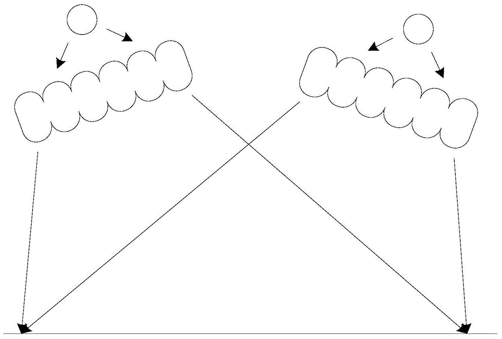
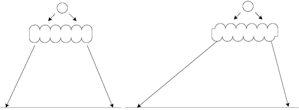
[0044] In order to achieve the purpose of the present invention, as image 3 , 4 As shown in and 6, in some embodiments of the fly-eye lens of the present invention, it includes a base 1 and a plurality of lens units 2 arranged on opposite sides of the base 1, and the lens units 2 are arranged obliquely relative to the base. Among them, the manufacturing materials and process of the fly-eye lens are no different from the prior art. The present invention is only a structural change, and the manufacturing materials and processes do not belong to the improvement of the present invention. Therefore, the specific manufacturing materials and processes used Processes and the like can be based on prior art, and will not be listed in detail here.

[0045] combine image 3 , 4As shown in and 6, the fly-eye lens is a double-sided fly-eye lens, which...


PUM


Abstract

The invention discloses a fly-eye lens which comprises a substrate and a plurality of lens units, wherein the lens units are distributed on two opposite surfaces of the substrate and are inclined relative to the substrate. The invention further discloses another fly-eye lens which comprises a substrate and a plurality of lens units, wherein the lens units are distributed on one surface of the substrate and are inclined relative to the substrate. Besides, the invention further discloses two optical systems comprising the two fly-eye lenses respectively. Compared with the prior art, uniformity and strength of illumination can be effectively improved, and meanwhile, the fly-eye lenses and the optical systems can be suitable for occasions requiring the gradient effect of light.

Description

technical field [0001] The invention relates to an illuminating device in the field of illumination, in particular to a fly-eye lens and a fly-eye lens optical system including the fly-eye lens. Background technique [0002] Fly-eye lens, also known as fly-eye lens, is composed of a series of identical micro-lenses, which can convert the incident circular spot with uneven light intensity distribution into a uniform rectangular spot. Fly-eye lenses and their optical systems are widely used in the field of realizing large-area uniform illumination, such as projectors and solar simulators. [0003] The currently used fly eye lenses mainly include double-sided fly eye lenses and single-sided fly eye lenses. The difference between the double-sided fly-eye lens and the single-sided fly-eye lens is that two sets of micro-lenses are integrated on the same transparent substrate, so the reliability and stability are higher in practical applications, while the single-sided double-row ...

Claims


Application Information

Patent Timeline
IPC IPC(8): G02B3/00G02B27/09
CPCG02B3/0037G02B27/0927G02B27/0961
Inventor 杨西斌高静熊大曦武晓东王沛沛张龙刘斌
Owner SUZHOU INST OF BIOMEDICAL ENG & TECH CHINESE ACADEMY OF SCI
Why Eureka
Try Eureka