High-power optical fiber cladding power stripper device

A fiber cladding and stripper technology, applied in the directions of light guides, optics, instruments, etc., can solve the problems of difficulty in making fiber tapers, difficult to remove low numerical aperture light, low power stripping efficiency, etc. The effect of stripping efficiency

Active Publication Date: 2015-04-29
BEIJING INST OF AEROSPACE CONTROL DEVICES
View PDF7 Cites 18 Cited by
  • Summary
  • Abstract
  • Description
  • Claims
  • Application Information

AI Technical Summary

Problems solved by technology

So far, there have been many documents and patents describing the devices and methods for removing the remaining pump light. The simplest method is to directly remove the low-refractive-index coating of the optical fiber, and then treat the part where the coating has been removed with a high-refractive-index material. Coating and curing (US patent US4678273), this method is difficult to remove low numerical aperture light, the power stripping efficiency is low and the light leakage point is too concentrated
In order to overcome the shortcomings of this method, the document "A novel method for stripping cladding lights in high power fiber lasers and amplifiers" J.Lightwave Technol.vol.30pp.3199-3202 uses hydrofluoric acid vapor and hydrofluoric acid solution to separate the double cladding The method of corroding the layered optical fiber into a fiber cone is used to strip the cladding power. This method can not only solve the problem of too concentrated light leakage but also remove the cladding light with low numerical aperture, but the fiber cone is difficult to manufacture.

Method used


Image

  • High-power optical fiber cladding power stripper device
  • High-power optical fiber cladding power stripper device
  • High-power optical fiber cladding power stripper device

Examples


Embodiment Construction

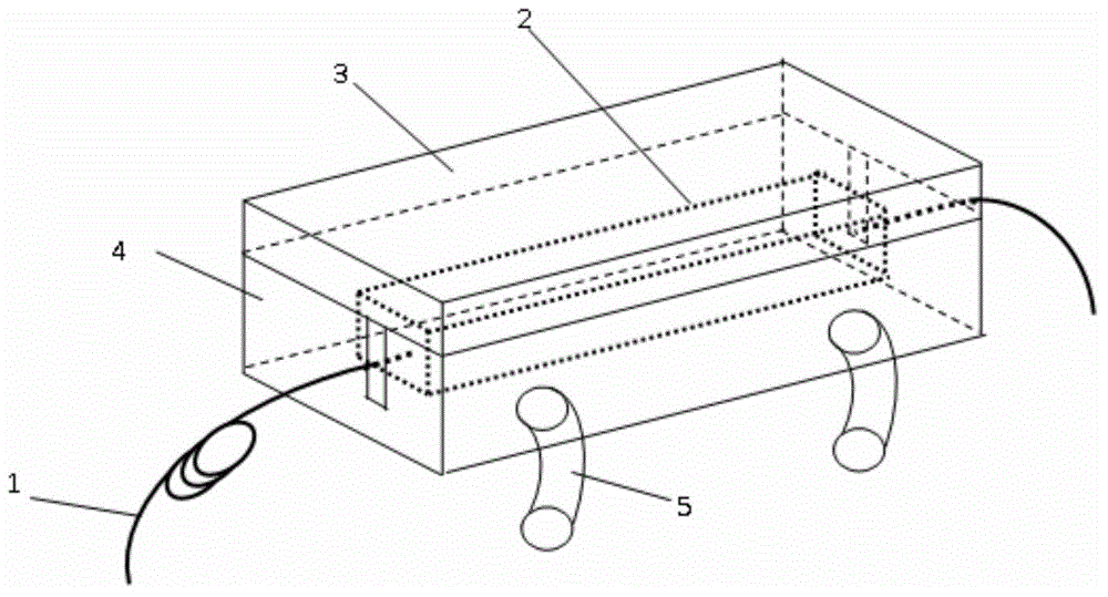
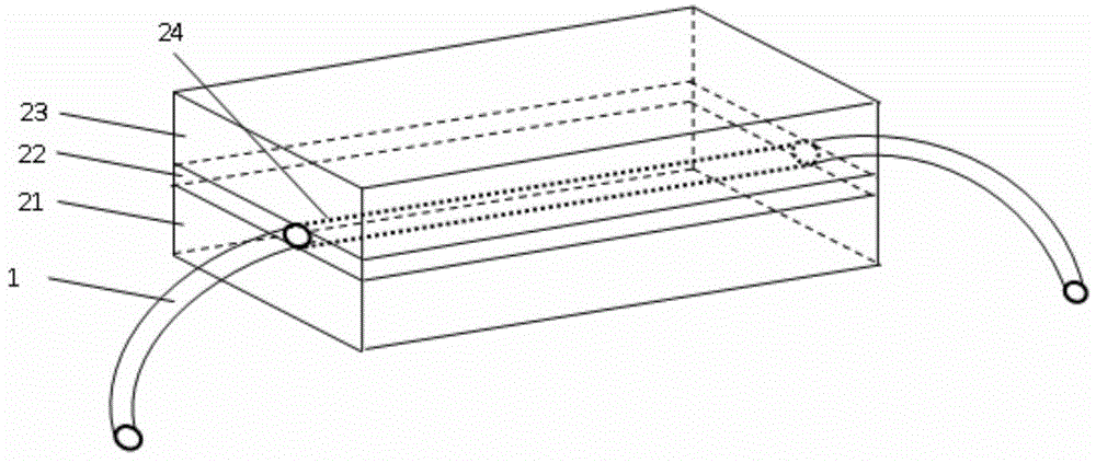
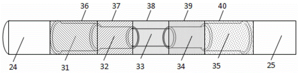
[0019] A high-power optical fiber cladding power stripper device such as figure 1 As shown, including the diameter r 0 Double-clad fiber 1, optical module 2, upper cover 3, water cooling base 4, water cooling tube 5, figure 1 Medium optical module 2 such as figure 2 As shown, the diameter including the inner cladding is r 0 Double-clad fiber 1, partially stripped inner cladding double-clad fiber 24, refractive index n L The light-transmitting material 21, the refractive index is n J The high refractive index optical gel 22, the refractive index is n K The light-transmitting material23. figure 2 Strip the inner cladding double-clad fiber 24 such as image 3 Shown.

[0020] In order to make the power stripper improve the stripping efficiency and make the inner cladding leakage light leak more evenly along the length of the optical fiber, such as image 3 The part of the double-clad inner cladding is stripped to form a stepped form 31, 32, 33, 34, 35, and coated with n 1 High refra...


PUM


Abstract

The invention relates to a high-power optical fiber cladding power stripper device. The high-power optical fiber cladding power stripper device comprises a double-cladding optical fiber (1), an optical module (2), an upper cover plate (3), a water cooling base (4) and a water cooling tube (5); the double-cladding optical fiber (1) penetrates through the optical module (2) and the water cooling base (4), the optical module (2) is arranged in the water cooling base (4), the upper portion of the water cooling base (4) is packaged through the upper cover plate (3) made of materials with the good radiating performance, and the water cooling tube (5) is installed at the lower portion of the water cooling base (4). According to the high-power optical fiber cladding power stripper device, an inner cladding of the optical fiber is stripped to be in a step type and is coated with high-refraction-index optical gel with different refraction indexes, light leaked through the inner cladding is leaked in a relatively-even mode along the length of the optical fiber, a three-layer-optical-waveguide optical module structure is constructed, and the light leaked through the inner cladding can be guided out through optical waveguides. In addition, heat is taken away in time through circulation water, and a stripper is prevented from being excessively high in temperature.

Description

Technical field [0001] The invention relates to a device device for removing residual pump light and cladding to transmit signal light, in particular to a high-power optical fiber cladding power stripper device. Background technique [0002] High-power fiber lasers have the advantages of high electro-optical conversion efficiency, good heat dissipation and output beam quality, high stability, etc., and are widely used in laser welding, drilling, surface treatment and marking fields. High-power fiber lasers usually use double-clad rare-earth doped fibers. The double-clad rare-earth doped fibers used today are generally composed of a core, an inner cladding, an outer cladding and a coating. This fiber structure only supports single Mode transmission, used to transmit and amplify signal light; inner cladding supports multi-mode transmission, used to couple and transmit pump light; this fiber structure not only ensures the beam quality of fiber laser, but also increases the pump and ...

Claims


Application Information

Patent Timeline
Patent Type & Authority Applications(China)
IPC IPC(8): G02B6/245
CPCG02B6/245
Inventor 李磐王金东王军龙李广于文鹏王学峰胡宝余
Owner BEIJING INST OF AEROSPACE CONTROL DEVICES
Why Eureka
Try Eureka