Tubular lens of image recognition system and image recognition system employing tubular lens

An image recognition and tube mirror technology, which is applied in the field of image recognition systems, can solve the problems of serious edge vignetting, elongated imaging distance, and reduced imaging quality, and achieves the effect of wide imaging distance range.

Active Publication Date: 2015-04-29
RAINTREE SCI INSTR SHANGHAI
View PDF9 Cites 1 Cited by
  • Summary
  • Abstract
  • Description
  • Claims
  • Application Information

AI Technical Summary

Problems solved by technology

[0009] If the existing design of the objective lens and tube lens is adopted, blindly elongating the imaging distance will result in reduced image resolution, uneven illumination, serious edge vignetting, etc., which will affect the accuracy of image recognition
If the imaging distance of objective lenses of different magnifications is also required to be adjustable at the same time, it cannot meet the requirements, because in general, when the imaging quality of an objective lens of one magnification is guaranteed, the imaging quality of another objective lens of different magnifications will be greatly reduced.

Method used


Image

  • Tubular lens of image recognition system and image recognition system employing tubular lens
  • Tubular lens of image recognition system and image recognition system employing tubular lens
  • Tubular lens of image recognition system and image recognition system employing tubular lens

Examples


Embodiment Construction

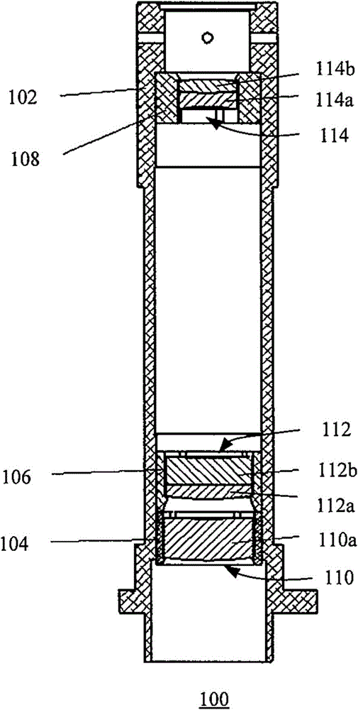
[0038] In the following detailed description of the embodiments, reference is made to the accompanying drawings that form a part hereof. The drawings show, by way of example, specific embodiments in which the invention may be practiced. The illustrated embodiments are not intended to be exhaustive of all embodiments according to the invention. It is to be understood that other embodiments may be utilized and structural or logical changes may be made without departing from the scope of the present invention. With respect to the drawings, directional terms, such as "below," "upper," "left," "right," etc., are used with reference to the orientation of the drawings being described. Since components of embodiments of the invention can be implemented in a variety of orientations, these directional terms are used for purposes of description, not limitation. Accordingly, the following detailed description is not intended to be limiting, and the scope of the invention is defined by t...


PUM


Abstract

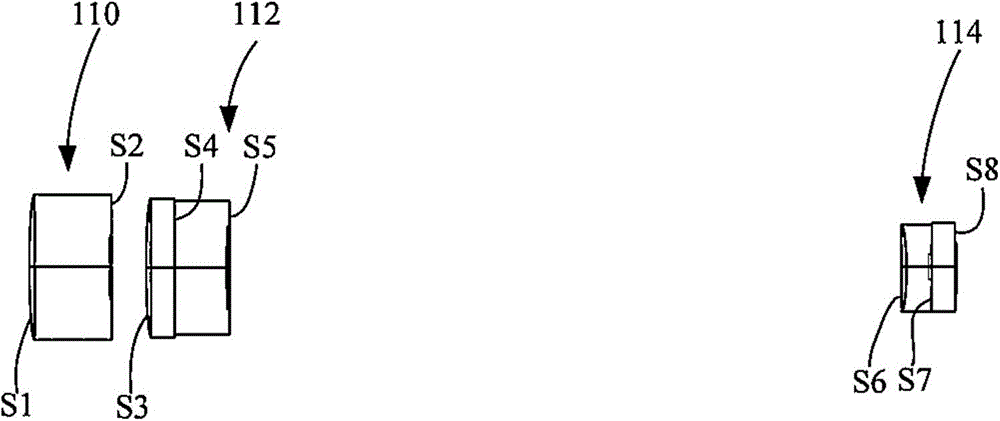
The invention discloses a tubular lens of an image recognition system. The tubular lens is used for cooperating with an object lens; the focal distance of the tubular lens is f; the tubular lens comprises a first lens group, a second lens group and a third lens group; a diaphragm can be flexibly arranged; the focal distance of the first lens group f1 is greater than 0.7f, but smaller than 1.2f, and the effective clear aperture of the first lens group is greater than 0.1f; the focal distance of the second lens group f2 is greater than 0, but smaller than 0.2f; the focal distance of the third lens group f3 is greater than -5f, but smaller than -2f; an interval between the first lens group and the second lens group on an optical axis is smaller than 0.05f; an interval between the second lens group and the third lens group on the optical axis is greater than 0.25f. According to the tubular lens, the first lens group adopts a lens made of a material with large clear aperture and high refractivity as a light beam constraining lens, so that a large-visual field light beam under a large interval can be effectively constrained; furthermore, the second lens group and the third lens group can compensate and optimize light rays, so that aberration is corrected and an image space visual field is controlled, and thus the requirement of high-quality imaging, in which the interval can be increased and the lens can be varied, is ultimately met.

Description

technical field [0001] The invention relates to the field of optical imaging, and an image recognition system applied to semiconductor measuring equipment, in particular to a tube mirror of the image recognition system and an image recognition system with the tube mirror. Background technique [0002] The development of semiconductor measurement equipment is a high-tech industry that is rapidly developing in China, involving many advanced frontier scientific fields. Image recognition technology is also an indispensable part of semiconductor measurement equipment. It mainly pursues high-resolution, low-distortion imaging quality in order to quickly and accurately identify images. [0003] The optical part of the image recognition system is mainly composed of two parts: the objective lens and the tube lens. At present, domestic and foreign image recognition systems use tube lenses ranging from two lenses to four or five lenses, which can achieve high resolution (1001p / mm and ...

Claims


Application Information

Patent Timeline
Patent Type & Authority Applications(China)
IPC IPC(8): G02B13/00G02B27/00
CPCG02B13/00G02B27/0025G02B27/0075
Inventor 叶薇薇李岩川
Owner RAINTREE SCI INSTR SHANGHAI
Why Eureka
Try Eureka