
A non-minimum phase hypersonic vehicle control method

A non-minimum phase, hypersonic technology, applied in the aerospace field, can solve problems such as uncertain hypersonic vehicles, achieve the effect of avoiding control allocation, realizing accurate feedback linearization, and overcoming the influence of uncertainty

Active Publication Date: 2017-06-27
BEIJING INST OF CONTROL ENG
View PDF5 Cites 0 Cited by
  • Summary
  • Abstract
  • Description
  • Claims
  • Application Information

AI Technical Summary

Problems solved by technology

[0003] The technical solution of the present invention is to provide a control method for a non-minimum phase hypersonic vehicle, which can solve the control problem of a non-minimum phase uncertain hypersonic vehicle to a certain extent

Method used


Image

  • A non-minimum phase hypersonic vehicle control method
  • A non-minimum phase hypersonic vehicle control method
  • A non-minimum phase hypersonic vehicle control method

Examples


Embodiment Construction

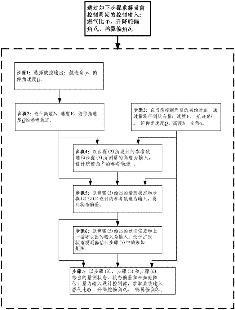
[0026] The present invention is described in detail below in conjunction with accompanying drawing, figure 1 It is a block flow diagram of the method of the present invention. The present invention comprises following 7 steps:

[0027] Calculate the control command in each control cycle of the hypersonic vehicle: gas ratio Φ, elevator deflection angle δ e , canard deflection angle δ c , realized through steps (1)-step (7).

[0028] Step (1) Select the controlled output: track angle γ and pitch angular velocity Q, and the controlled output V of the joint system, so that the first four equations in formula (1) are three-input and three-output, the input is the gas ratio Φ, the elevator Angle δ e , canard deflection angle δ c , which can be designed using feedback linearization techniques.

[0029] In the present invention, the air-breathing hypersonic vehicle longitudinal channel model is considered as follows:

[0030]

[0031] In the formula: V, γ, θ, Q, h represent ...


PUM


Abstract

Disclosed is a non-minimum-phase hypersonic vehicle control method. The method includes the steps: (1) selecting a track angle gamma and a pitching angular velocity Q as controlled output, designing a reference track of controlled output height h, velocity V and the pitching angular velocity Q; (2) designing a reference track of the track angle gamma; (3) at the initial moment of a current control cycle, measuring state variables of the velocity V, track angle gamma, pitching angular velocity Q, attack angle alpha and height h of a hypersonic vehicle; (4) measuring a state error formula I which satisfies a dynamic equation formula II; (5) estimating an unknown matrix in the step (4); (6) designing a control law formula III, wherein k<0 and k is a constant, acquiring a control command of the current control cycle with the control law, controlling the vehicle according to the control command, entering a next control cycle and shifting a step (2) for looping execution.

Description

technical field [0001] The invention belongs to the field of aerospace, and relates to a non-minimum phase hypersonic vehicle control method. Background technique [0002] The air-breathing hypersonic vehicle has a high flight speed and has received widespread attention from various military powers. Due to the "airframe-engine integration" design technology and the complex flight environment, the dynamics of the aircraft have the characteristics of strong coupling, strong nonlinearity, and strong uncertainty. Due to the special structure of the aircraft itself and the uncertainty of the atmospheric airflow, there is a coupling between the aircraft elevator and the aerodynamic force, which makes the aircraft exhibit non-minimum phase characteristics. These characteristics bring great difficulties to its control law design. Contents of the invention [0003] The technical problem to be solved by the present invention is to provide a control method of a non-minimum phase hy...

Claims


Application Information

Patent Timeline
Patent Type & Authority Patents(China)
IPC IPC(8): G05D1/00
Inventor 孟斌李公军姜甜甜
Owner BEIJING INST OF CONTROL ENG
Learn More