
Contact mechanism of switching device capable of realizing three states

A technology of switching electrical appliances and three states, applied in the field of power conversion switching electrical appliances, can solve the problems of limited effective rotation angle range of moving contacts, unsuitable switching electrical appliances, increased cost and possible failure probability, etc.

Active Publication Date: 2015-04-29
SCHNEIDER WINGOAL TIANJIN ELECTRIC EQUIP
View PDF6 Cites 2 Cited by
  • Summary
  • Abstract
  • Description
  • Claims
  • Application Information

AI Technical Summary

Problems solved by technology

However, the contact unit of this structure also has disadvantages: 1. There are two knife-type plug-in static contacts, and the structure is relatively complicated, which increases the cost and the possibility of failure; 2. Two knife-type contacts are arranged on both sides of the moving contact group Type plug-in static contact and two finger-type snap-in static contacts, and a spring and bracket should be set between the knife-type plug-in static contact and finger-type snap-in static contact. Therefore, the remaining space for the moving contact The effective rotation angle range is relatively limited, and can only reach a maximum angle range of 90 degrees. It is not suitable for switching appliances that require a double-open state in addition to the main close and standby close.

Method used


Image

  • Contact mechanism of switching device capable of realizing three states
  • Contact mechanism of switching device capable of realizing three states
  • Contact mechanism of switching device capable of realizing three states

Examples


Embodiment Construction

[0106] It should be noted that, in the case of no conflict, the embodiments of the present invention and the features in the embodiments can be combined with each other.

[0107] The present invention will be described in detail below with reference to the accompanying drawings and examples.

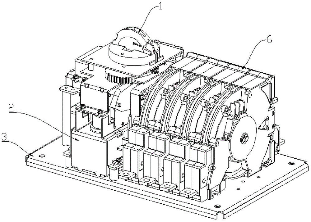
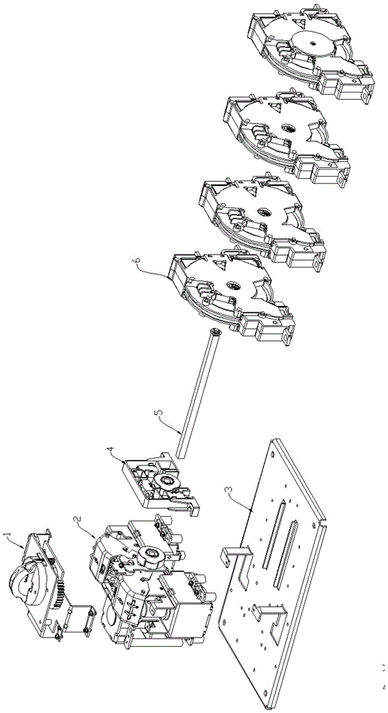
[0108] Such as figure 1 As shown, the automatic / manual switch conversion electrical appliance includes a manual operating mechanism 1, an operating mechanism 2, a base plate 3, a position feedback assembly 4, a main shaft 5 and a contact mechanism 6. The operating mechanism 2 drives the main shaft 5 to rotate, and the main shaft 5 The rotation drives the contacts of the compound contact mechanism 6 to realize the connection of the main power supply (commonly used power supply) (i.e. "main closing"), the main power supply and the backup power supply are both broken (i.e. "double points"), and the backup power supply is connected (i.e. "Preparation") transitions between the three states. ...


PUM


Abstract

The invention provides a contact mechanism of a switching device capable of realizing three states. The contact mechanism comprises multiple contact units sequentially arranged in parallel, wherein each contact unit comprises a movable contact group and a static contact group; mirror images on the two sides of the central part of the movable contact group symmetrically extend out of a movable contact plate part; each movable contact plate part further comprises a beat type contact and an arc-shaped knife type inserting contact which are fixedly arranged on the two sides of the external end part of the movable contact plate part respectively and have the same orientation; each static contact group comprises two finger-type beat type static contacts and one knife type inserting static contact, and the two finger-type beat type static contacts are arranged on the two sides of the central part of the movable contact group respectively. According to the invention, the contact mechanism can effectively reduce electrical wear generated when a contact is closed or disconnected, enables the rotating angle of the movable contact group to be enlarged to an angle nearly 180 degrees, is very suitable for the switching device capable of switching among three states, effectively avoids the point contact phenomenon caused by machining error and other cumulative errors, ensures contact pressure, and enables a movable contact and a static contact to keep excellent surface contact.

Description

technical field [0001] The invention belongs to the field of power conversion switch electric appliances. Background technique [0002] Power conversion switch electrical appliance is a widely used terminal electrical appliance. According to the control mode, it can be divided into three types: automatic type, manual type, and automatic / manual combined type. It mainly controls the action of the contact system through the operating mechanism to connect Or cut off the main power supply and backup power supply to ensure the safety of the power system and the continuity of production. [0003] The contact mechanism is a mechanism that is directly connected to the power supply in the transfer switch electrical appliance. The contacts in the contact mechanism are divided into two types: moving contacts and static contacts according to whether they move. There are two types of plug-in type and knife-type plug-in type. The finger-type clap-type contacts can resist burning under the...

Claims


Application Information

Patent Timeline
IPC IPC(8): H01H1/14H01H1/42H01H1/50H01H9/24
CPCH01H1/14H01H1/42H01H1/50H01H9/24
Inventor 陈红群岳鹏温栋亮娄建琴张鑫王美华肖平
Owner SCHNEIDER WINGOAL TIANJIN ELECTRIC EQUIP
Learn More