Novel coupled feed antenna aiming at clearance-free rear metal shell

A metal back shell, coupled feed technology, applied in the field of antennas, can solve the problems affecting the consistency of the metal back shell, poor antenna radiation performance, large space, etc., to solve the problem of antenna design, widen the antenna bandwidth, good bandwidth and Effects of Radiation Properties

Inactive Publication Date: 2015-04-29
SHANGHAI AMPHENOL AIRWAVE COMM ELECTRONICS CO LTD
View PDF6 Cites 4 Cited by
  • Summary
  • Abstract
  • Description
  • Claims
  • Application Information

AI Technical Summary

Problems solved by technology

[0004] The purpose of the present invention is to provide a new type of coupling feed antenna for metal back shells without headroom, so as to solve the problem of poor antenna radiation performance, large space occupation or affecting the overall metal back shell of mobile communication devices with metal back shells. problem of consistency

Method used


Image

  • Novel coupled feed antenna aiming at clearance-free rear metal shell
  • Novel coupled feed antenna aiming at clearance-free rear metal shell
  • Novel coupled feed antenna aiming at clearance-free rear metal shell

Examples


Embodiment Construction

[0022] In order to better illustrate the present invention, the present invention will be described in detail with a preferred embodiment and with accompanying drawings, specifically as follows:

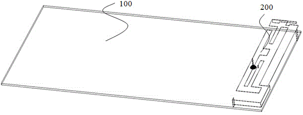
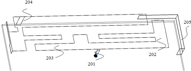
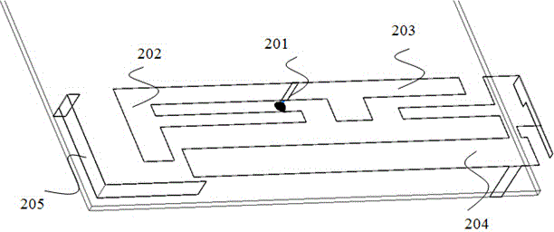
[0023] Such as figure 1 As shown, the novel coupled feeding antenna provided in this embodiment for the metal back shell without headroom includes a PCB board 100 and an antenna body 200 disposed on the PCB board. Such as figure 2 As shown, the antenna main body 200 includes a feed structure, and a feed point 201 is arranged on the feed structure, and the feed point 201 divides the feed structure into a first feed branch 202 and a second feed branch 203, wherein the first feed The electrical branch 202 is coupled to the second parasitic coupling branch 205 , the first feeding branch 202 is coupled to the first parasitic coupling branch 204 , and the second feeding branch 203 is coupled to the first parasitic coupling branch 204 . The second parasitic coupling branch 205 and the fi...


PUM


Abstract

The invention provides a novel coupled feed antenna aiming at a clearance-free rear metal shell. The novel coupled feed antenna comprises a PCB and an antenna main body arranged on the PCB, wherein the antenna main body is provided with a feed point, a first feed branch and a second feed branch; a first intercoupling branch is coupled with the first feed branch and the second feed branch; a second intercoupling branch is coupled with the first intercoupling branch, wherein the first intercoupling branch and the second intercoupling branch are arranged at the part close to the edge of the PCB. By the coupled feed and the reasonable parasitic element configuration for the antenna, the bandwidth of the antenna is widened greatly, and the design difficulty of the antenna on the whole rear metal shell is solved effectively. Simulation and actual measurement show that the bandwidth of the antenna is relatively wide, the efficiency is relatively good, and the performances of the antenna at both the high-frequency section and the low-frequency section of mobile communication can well meet the requirement for mobile communication equipment.

Description

technical field [0001] The invention relates to an antenna, in particular to a novel coupling feed antenna for a metal back shell without headroom. Background technique [0002] With the continuous progress of society and the rapid development of science and technology, mobile communication equipment has become an indispensable part of people's office life, and the current mobile communication equipment with metal texture is generally favored by the majority of users, and mobile communication equipment with metal casings has become a mainstream product. Therefore, the all-metal back shell machine has become one of the main research and development directions of mobile communication equipment manufacturers, but the metal back shell of mobile communication equipment has caused the deterioration of the antenna system environment and the decline of antenna performance. [0003] Existing mobile communication devices with metal back shells need to open a slit on the back shell (s...

Claims


Application Information

Patent Timeline
Patent Type & Authority Applications(China)
IPC IPC(8): H01Q1/36H01Q1/50H01Q5/10H01Q5/20H01Q5/385
Inventor 徐春阳王君翊田志明胡沥
Owner SHANGHAI AMPHENOL AIRWAVE COMM ELECTRONICS CO LTD
Why Eureka
Try Eureka