Pin pressing device for commutator

The technology of a presser foot device and a commutator is applied in the field of presser foot devices, which can solve the problems of coil breakage and breakage at the bend of hook feet, and achieve the effects of increasing service life, reducing the number of breaks, and reducing the rate of defective products.

Inactive Publication Date: 2015-04-29
HUARUI ELECTRICAL APPLIANCE
View PDF4 Cites 2 Cited by
  • Summary
  • Abstract
  • Description
  • Claims
  • Application Information

AI Technical Summary

Problems solved by technology

One end of the hook-type commutator is provided with a hook foot. The processing method of the hook foot in the prior art generally adopts a bending machine for direct bending, resulting in a protrusion formed at the bend on the hook foot, and the bend at the bend The lateral width is larger than the lateral width of the commutator segment. During the winding process of the commutator, the protrusions will cause the coil to break, and even cause frequent breakage at the bend of the hook foot.

Method used


Image

  • Pin pressing device for commutator
  • Pin pressing device for commutator
  • Pin pressing device for commutator

Examples


Embodiment Construction

[0016] The following are specific embodiments of the present invention and in conjunction with the accompanying drawings, the technical solutions of the present invention are further described, but the present invention is not limited to these embodiments.

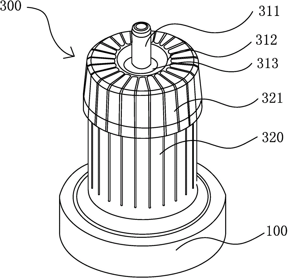
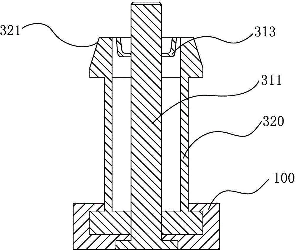
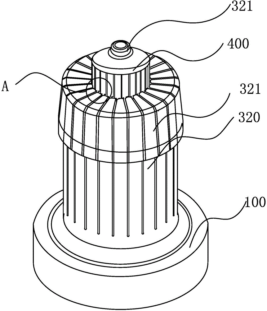
[0017] Such as Figure 1 to Figure 5 As shown, the presser foot device for the commutator 400 includes a base body 100, a lower die 300 disposed on the base body 100 and used for installing the commutator 400, and an upper die 200 matched with the lower die 300, and the upper die 200 Including the pressure cylinder 210 and the connecting shaft 220, the lower mold 300 includes a mold core and a number of mold pieces 320 uniformly surrounding the mold core. There is a gap between the mold pieces 320. When the commutator 400 is set on the lower mold 311 The hook legs of the commutator 400 are clamped in the gap, and the downward movement of the upper mold 200 can make the mold piece 320 move closer to the mold core in the rad...


PUM


Abstract

The invention provides a pin pressing device for a commutator, belongs to the technical field of commutator equipment and solve the problem of poor extrusion effect of an existing pin pressing device for the commutator. The pin pressing device for the commutator comprises a base body, a lower mould which is arranged on the base body and is used for mounting the commutator and an upper mould which is matched with the lower mould; the upper mould comprises a pressing cylinder and a connecting shaft; the lower mould comprises a mould core and a plurality of mould plates which uniformly encircle the periphery of the mould core; a gap is formed among the mould plates; when the commutator is arranged on the lower mould, hook pins of the commutator are clamped in the gap, and the upper mould moves downwards to enable the mould plates to be close to the mould core in a radial direction and to extrude the hook pins to be in a boss shape. The pin pressing device for the commutator has the advantages of good extrusion effect and capability of preventing the hook pins of the commutator from being broken.

Description

technical field [0001] The invention belongs to the technical field of commutator equipment, and relates to a presser foot device for a commutator. Background technique [0002] At present, there are many types of commutators used for motor armatures, such as slot-type commutators, hook-type commutators, K-type commutators, etc., each commutator includes a commutator base and a Multiple commutator segments on the base body. One end of the hook-type commutator is provided with a hook foot. The processing method of the hook foot in the prior art generally adopts a bending machine for direct bending, resulting in the outward protrusion of the bending part on the hook foot, and the bending part The lateral width is greater than that of the commutator segment. During the winding process of the commutator, the protrusions will cause the coil to break, and even cause frequent breakage at the bend of the hook foot. Contents of the invention [0003] The object of the present inv...

Claims


Application Information

Patent Timeline
Patent Type & Authority Applications(China)
IPC IPC(8): H01R43/06
CPCH01R43/06H01R2201/10
Inventor 赵吉峰孙瑞娣张宏儿陈岳祥张均德
Owner HUARUI ELECTRICAL APPLIANCE
Why Eureka
Try Eureka