Stator winder

A stator winding and stator technology, applied in the direction of electromechanical devices, manufacturing motor generators, electrical components, etc., can solve the problems of inability to save metal consumables, low efficiency of manual winding, unstable precision, etc., to improve synchronous production efficiency , save labor costs and material costs, and improve production efficiency

Active Publication Date: 2015-04-29
佛山市吉星家电有限公司
View PDF6 Cites 12 Cited by
  • Summary
  • Abstract
  • Description
  • Claims
  • Application Information

AI Technical Summary

Problems solved by technology

[0004] However, there is no automatic and high-speed winding machine for this new type of stator in the existing technology, and the efficiency of manual winding is too low, the cost is too high, the accuracy is unstable, and the saving of metal consumables cannot be realized.

Method used


Image

  • Stator winder
  • Stator winder
  • Stator winder

Examples


Embodiment Construction

[0033] The present invention is described in further detail by the following examples.

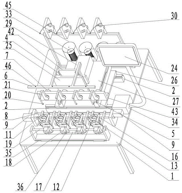
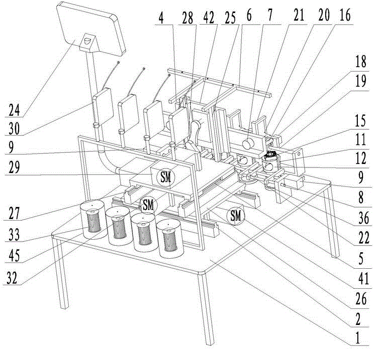
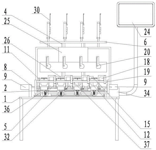
[0034] see Figure 1 to Figure 7 As shown, a stator winding machine is provided with a frame 1, a fixture table, a workbench and a console.

[0035]The fixture table is provided with a stator fixture seat 12, the stator fixture seat 12 is hollow and has a stator insertion groove 13, the stator body 15 is placed in the stator insertion groove 13, and the stator fixture seat 12 side is provided with a stator fixing device to clamp the stator body 15 , the stator clamp seat 12 is provided with a wire clamping / breaking device, and the lower part of the stator clamp seat 12 is provided with a stator clamp seat drive motor 36 to drive the stator clamp seat 12 to rotate and reciprocate; the stator fixing device includes a clamping claw 11, a connecting rod 8 1. Clamping claw cylinder 9, clamping claw 11 is installed on the side of the stator clamp seat 12, the shape of the upper part of the clam...


PUM


Abstract

Provided is a stator winder. The stator winder comprises a rack, a clamp station, a workbench and a controlling station. The clamp station is provided with a stator clamp seat, a stator fixing device, a wire clamping or wire breaking device. The workbench is provided with a wire feeding device, a wire winding device, an X-axis moving device capable of doing left and right reciprocating motion, a Y-axis moving device capable of doing forward and backward reciprocating motion and a Z-axis moving device capable of doing upward and downward reciprocating motion. A Z-axis servo motor drives a cam crank connecting rod mechanism to move, and drives a Z-axis planker to carry out the upward and downward reciprocating motion. The workbench is adjacent to the clamp station. Swing arms of the wire winding device are in the shape of the capital 'pi'. Wire winding needles are vertically arranged on the sides of front arms of the swing arms. The front arms of the swing arms and the wire winding needles can stretch into or moving apart from the hollow portion and the upper portion of a stator body on the stator clamp seat to conduct the wire winding process. According to the stator winder, the mechanical, fully automatic, high speed and accurate varnished wire winding process can be conducted on the stator body of a novel fan motor, so that the manual operation or intervention is not needed during the whole wire winding process.

Description

technical field [0001] The invention relates to the technical field of fan motor manufacturing, in particular to a stator winding machine. Background technique [0002] see Figure 1~Figure 2 As shown, an existing new fan motor stator is composed of a stator body 15 and primary and secondary windings. The stator body 15 is composed of a stator core 101 and an insulating skeleton 102 matched with the stator core. Eight winding cores 131, 132, 133, 134, 135, 136, 137, 138 and eight empty slots 104 are arranged in equal parts, each winding core is rectangular, each empty slot is fan-shaped, and the insulation frame Eight groups of outer baffles 105 and six terminal posts 151, 152, 153, 154, 155, 156 are arranged on the outer circumference, and one main winding 141 is wound in series on odd winding cores, and three auxiliary windings 142, 143, 144 are respectively wound in series on the even-numbered winding cores 103 in sequence, and the connected enameled wires between the wi...

Claims


Application Information

Patent Timeline
Patent Type & Authority Applications(China)
IPC IPC(8): H02K15/08
Inventor 黄宝钗吴树填曾显祥张兆芝
Owner 佛山市吉星家电有限公司
Why Eureka
Try Eureka