
Clock gating trigger

A technology of gated clocks and flip-flops, applied in the direction of electrical pulse generator circuits, etc., can solve the problems of complex circuit topology, wasteful consumption of power consumption, circuit delay and large power consumption, etc. The effect of small delay and power consumption, improving the running speed

Active Publication Date: 2015-04-29
临沂经开财金投资发展有限公司
View PDF3 Cites 5 Cited by
  • Summary
  • Abstract
  • Description
  • Claims
  • Application Information

AI Technical Summary

Problems solved by technology

The gate voltage bootstrap type gated clock flip-flop and the transmission tube type gated clock flip-flop use a large number of MOS tubes, and the circuit topology is relatively complex, resulting in wasteful consumption of power consumption, circuit delay and power consumption bigger

Method used


Image

  • Clock gating trigger
  • Clock gating trigger
  • Clock gating trigger

Examples


Embodiment

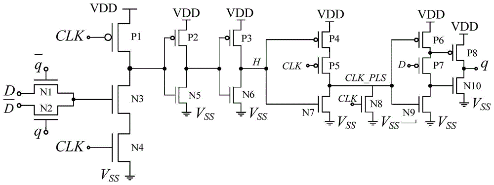
[0015] Example: as image 3 As shown, a gated clock flip-flop includes a first PMOS transistor P1, a second PMOS transistor P2, a third PMOS transistor P3, a fourth PMOS transistor P4, a fifth PMOS transistor P5, a sixth PMOS transistor P6, and a seventh PMOS transistor P6. PMOS transistor P7, eighth PMOS transistor P8, first NMOS transistor N1, second NMOS transistor N2, third NMOS transistor N3, fourth NMOS transistor N4, fifth NMOS transistor N5, sixth NMOS transistor N6, seventh NMOS transistor N7, the eighth NMOS transistor N8, the ninth NMOS transistor N9 and the tenth NMOS transistor N10;

[0016] The source of the first PMOS transistor P1, the source of the second PMOS transistor P2, the source of the third PMOS transistor P3, the source of the fourth PMOS transistor P4, the source of the sixth PMOS transistor P6 and the eighth PMOS transistor P8 The sources of all are connected to the power supply; the gate of the first PMOS transistor P1, the gate of the fifth PMOS ...

Embodiment 2

[0021]Embodiment 2: This embodiment is basically the same as Embodiment 1, except that in this embodiment, the first PMOS transistor P1, the second PMOS transistor P2, the third PMOS transistor P3, the fourth PMOS transistor P4, and the fifth PMOS transistor P5, sixth PMOS transistor P6, seventh PMOS transistor P7, eighth PMOS transistor P8, first NMOS transistor N1, second NMOS transistor N2, third NMOS transistor N3, fourth NMOS transistor N4, fifth NMOS transistor N5, The channel lengths of the sixth NMOS transistor N6, the seventh NMOS transistor N7, the eighth NMOS transistor N8, the ninth NMOS transistor N9 and the tenth NMOS transistor N10 are all 90 nm under the SMIC 90 nm standard process.

[0022] Under the SMIC130nm and SMIC90nm standard processes, compare the gated clock flip-flop of the present invention with respect to the two traditional gated clock flip-flops, the transmission tube gated clock flip-flop and the gate voltage bootstrap gated clock flip-flop. perf...


PUM


Abstract

The invention discloses a clock gating trigger. According to the clock gating trigger, a first PMOS (P-channel Metal Oxide Semiconductor) tube, a second PMOS tube, a third PMOS tube, a fourth PMOS tube, a fifth PMOS tube, a third NMOS (N-channel Metal Oxide Semiconductor) tube, a fifth NMOS tube, a sixth NMOS tube, a seventh NMOS tube and an eighth NMOS tube are arranged to form a short pulse generating circuit, wherein the short pulse generating circuit enables the high level width of a clock signal to be as narrow as possible, so that the clock gating trigger approximately becomes an edge trigger, and the running speed can be increased; meanwhile, compared with the conventional clock gating trigger, the quantity of the used MOS tubes can be reduced, the running speed is increased, and the circuit power consumption is reduced; more importantly, the circuit adopts the clock-gating technology, only when the MOS tubes is overturned, the clock can be correspondingly overturned, so that a lot of idle overturn can be reduced, and the power consumption can be reduced. The clock gating trigger has the advantages of low circuit delay and low power consumption.

Description

technical field [0001] The present invention relates to a flip-flop, in particular to a gating clock flip-flop. Background technique [0002] In digital circuits, the basic working signals are binary digital signals and switching logic signals, and the flip-flop is a basic logic unit that has a memory function and can store these signals. The flip-flop has the function of maintaining the result of the previous input signal before the arrival of the next input signal, that is, the memory function of the circuit is one of the most widely used gate circuits at present. As the computing speed of the microprocessor becomes faster and faster, the demand for flip-flops is also higher and higher, and its speed, power consumption, and area performance will directly affect the overall performance of the entire integrated circuit. [0003] The gated clock is introduced into the gated clock flip-flop to selectively stop the clock of the internal circuit within a certain period of time,...

Claims


Application Information

Patent Timeline
Patent Type & Authority Applications(China)
IPC IPC(8): H03K3/02
Inventor 胡建平程伟
Owner 临沂经开财金投资发展有限公司
Learn More