
Concentrated solar power generation system

A solar thermal power generation, solar technology, applied in the direction of solar thermal power generation, solar heating system, solar thermal energy, etc., can solve the problems of increased cost, inability to generate electricity, low power generation efficiency, etc., and achieve the effect of increasing heat loss

Inactive Publication Date: 2015-04-29
金振暎 +2
View PDF9 Cites 11 Cited by
  • Summary
  • Abstract
  • Description
  • Claims
  • Application Information

AI Technical Summary

Problems solved by technology

This prior art has the following disadvantages: since a reflective plate comprising a plurality of reflective mirrors is provided, and a heat collector is provided at a predetermined distance from said reflective plate, a large area of ​​space for light collection is required, and Causes an increase in the cost required for installation, and since the reflector and the heat collector are fixed at a predetermined distance, heat loss occurs and the concentration efficiency decreases
This prior art has the following disadvantages: a large area of ​​space is required to install a tower with a heat collector and a plurality of reflectors, the cost required for installation increases, and since the reflector and the heat collector are fixed at a predetermined distance , resulting in heat loss and reduced light-gathering efficiency
This prior art has the following problems. Since the steam generator is installed at a predetermined distance from the square Fresnel lens, it is disadvantageous to secure a space for installation, and power generation cannot be generated when there is no sunlight. The power generation efficiency is low
[0010] As described above, the prior art solar thermal power generation system exposed problems such as securing a separate space required for installation and reduced efficiency of light concentration and power generation

Method used


Image

  • Concentrated solar power generation system
  • Concentrated solar power generation system
  • Concentrated solar power generation system

Examples


Embodiment Construction

[0037] Hereinafter, embodiments of the concentrating solar thermal power generation system of the present invention are described in detail with reference to the accompanying drawings.

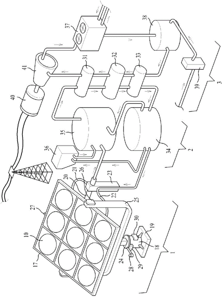
[0038] exist figure 1 Among them, the present invention can be divided into a heat collecting device 1 that gathers sunlight and collects heat, a heat storage device 2 that stores heat generated by the heat collecting device, and steam generated by heat exchange of heat stored in the heat storage device. A heat exchange device 3 that operates a steam turbine to generate electricity.

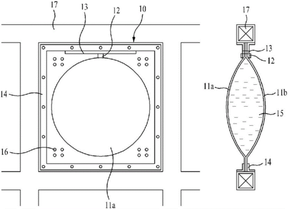
[0039] The heat collecting device 1 concentrates sunlight while tracking the sun. In the heat collecting device 1 , at least one concentrator 10 for concentrating sunlight is assembled in a grid-shaped housing 17 . The heat collector 70 is located at a predetermined distance from the concentrator 10 . In other words, preferably one heat collector 70 is provided for one concentrator 10 . Flows of the heating m...


PUM


Abstract

The present invention comprises: a heat collecting device for generating high-temperature superheated steam by concentrating solar light in at least one assembled concentrator while tracking the sun and by heating a heating medium supplied to a heat collector so as to heat the heat collector which is positioned at a predetermined distance from the concentrator; a heat accumulating device for storing heat by heating a heat storage tank for a floor heating method using the superheated steam generated by the heat collecting device; a heat exchange device for carrying out heat exchange with the high-temperature and high-pressure saturated steam which is capable of driving a power generator by operating a steam turbine using the heat stored in the heat accumulating device; and a heating medium water tank for supplying a low-temperature heating medium to the heat collecting device and the heat accumulating device, and storing the heating medium flowing through the heat exchange device. Thus, the present invention has high light concentrating efficiency by minimizing heat loss, can use latent heat even at night or in the event of rain by storing heat in the heat storage tank for a floor heating method, provides continuous power generation by operating a steam turbine using saturated steam generated from the heat exchange with the latent heat of the heat storage tank, and can be used in various fields, such as air conditioning and heating, culinary, and the like.

Description

technical field [0001] The present invention relates to a system for generating electricity by concentrating solar heat, and more particularly to a system for concentrating light energy emitted by the sun to produce superheated steam at high temperature and pressure, accumulating heat and then utilizing the saturation generated by heat exchange Concentrating solar thermal power generation system that generates electricity from steam. Background technique [0002] With the development of civilization, the use of fossil fuels has increased dramatically, which has led to serious environmental pollution problems and global warming, which has become a hot topic in the international community. dissenting views related to national interests are going in an undesired direction. Accordingly, various attempts to develop new renewable energy have been made to actively cope with global warming and environmental problems. [0003] New renewable energy refers to energy that is utilized ...

Claims


Application Information

Patent Timeline
IPC IPC(8): F24J2/04F24J2/06F24J2/34F24J2/02F24S20/30F24S23/00
CPCY02E10/46Y02E10/47F03G6/067F24S20/20F24S30/452F24S23/31F24S23/30F03G6/00Y02E10/40
Inventor 金振暎李守子金贤智
Owner 金振暎
Learn More