Combustion pressure sensor

A technology of combustion pressure and sensors, applied in instruments, internal combustion engine testing, measuring devices, etc., can solve the problems of weakened bellows function, failure to detect combustion pressure, and obstruction of bellows shrinkage, so as to ensure installation strength, achieve stability and reliability performance, and the effect of improving detection sensitivity

Inactive Publication Date: 2015-04-29
CITIZEN FINEDEVICE +1
View PDF14 Cites 3 Cited by
  • Summary
  • Abstract
  • Description
  • Claims
  • Application Information

AI Technical Summary

Problems solved by technology

[0012] However, the conventional combustion pressure sensor shown in Patent Document 1 holds the heating rod for detecting the combustion pressure through the bellows. Therefore, there is a problem that the combustion residue in the engine combustion chamber adheres to and accumulates in the low-lying parts of the bellows. The function is weakened, which prevents the bellows from shrinking and cannot detect the combustion pressure

Method used


Image

  • Combustion pressure sensor
  • Combustion pressure sensor
  • Combustion pressure sensor

Examples


Embodiment approach 1

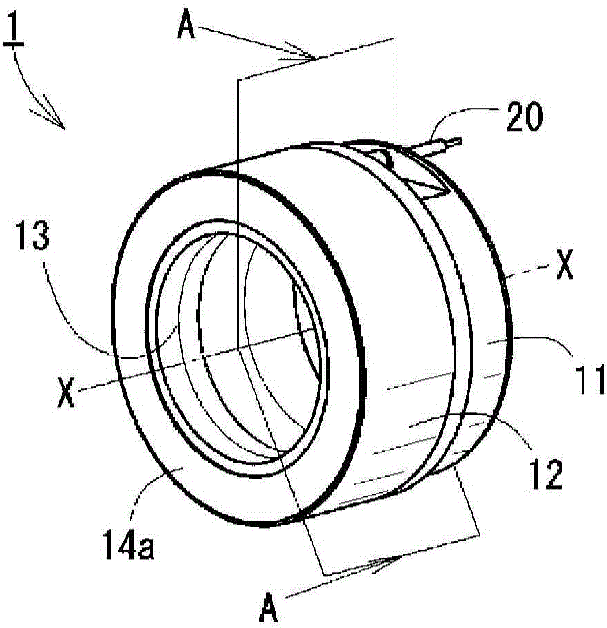
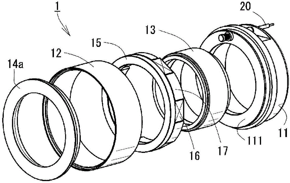
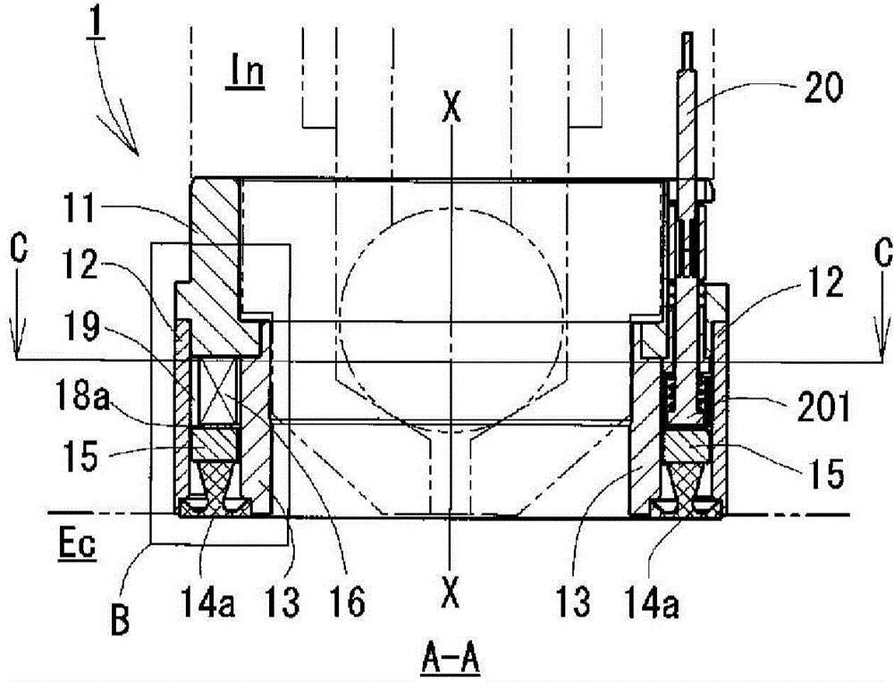
[0044] figure 1 is a perspective view showing the appearance of the combustion pressure sensor according to Embodiment 1 of the present invention, figure 2 is an exploded perspective view of the combustion pressure sensor, image 3 is along figure 1 The cross-sectional view of the A-A section in , the injector as a functional part is represented by an imaginary line (two-dot dash line), Figure 4 yes image 3 Partial enlarged cross-sectional view of Part B of Figure 5 is along image 3 Cutaway view of the C-C section in . In addition, the same code|symbol is attached|subjected to the same structural member in each figure, and overlapping description is abbreviate|omitted.

[0045] Below, through Figure 1 to Figure 5 The overall structure of the combustion pressure sensor according to Embodiment 1 will be described.

[0046] Such as figure 1 As shown, the combustion pressure sensor 1 according to Embodiment 1 of the present invention has a cylindrical shape with the...

Embodiment approach 2

[0068]Embodiment 2 is the same as Embodiment 1. It is a combustion pressure sensor composed of a ring-shaped cylinder that can be installed at the end of a functional component in the engine combustion chamber. The difference from Embodiment 1 is only the shape of the diaphragm. Regarding other The structural members are all the same.

[0069] Figure 6 is a perspective view showing the appearance of the combustion pressure sensor 2 according to Embodiment 2 of the present invention, Figure 7 is the same as that of Embodiment 1 Figure 4 The same partial enlarged cross-sectional view. In addition, the same code|symbol is attached|subjected to the same structural member in each figure, and overlapping description is abbreviate|omitted.

[0070] Below, through Figure 6 , Figure 7 The overall structure of the combustion pressure sensor according to Embodiment 2 will be described.

[0071] Such as Figure 6 As shown, the combustion pressure sensor 2 in Embodiment 2 of th...

Embodiment approach 3

[0076] Embodiment 3 is a combustion pressure sensor having the same shape as Embodiment 2. The difference from Embodiment 2 is that only part of the electrode layer is replaced with an electrode member, and all other structural members are the same.

[0077] Figure 8 is the same as that of Embodiment 2 Figure 7 The same partial enlarged cross-sectional view. In addition, the same code|symbol is attached|subjected to the same structural member in each figure, and overlapping description is abbreviate|omitted.

[0078] Below, through Figure 8 The overall structure of the combustion pressure sensor according to Embodiment 3 will be described.

[0079] Such as Figure 8 As shown, the difference from Embodiment 2 is that the electrode layer 18a is replaced with the electrode member 18b. That is, the electrode member 18b is composed of an insulating portion 181 and an electrode 182 formed on one surface of the insulating portion 181, such as FPC (Flexible printed circuits), ...


PUM


Abstract

A combustion pressure sensor comprising a ring-shaped cylinder body is mounted to the front end outer peripheral section of a function component mounted to the combustion chamber of an engine and detects the combustion pressure in the combustion chamber. The cylinder body has a sealed space formed between an outer cylinder member and an inner cylinder member, which are coaxial with each other, and one side of the sealed space is sealed with a ring-shaped diaphragm and the other side of the sealed space is sealed with a ring-shaped support member. The diaphragm has, on the combustion chamber side, a ring-shaped pressure receiving section which receives pressure from the outside, and diaphragm also has, on the back surface side, a ring-shaped transmission section. A pressure transmission member and a pressure detection element are provided in the sealed space. The transmission section of the diaphragm, the pressure transmission member, the pressure detection element, and the support member are sequentially in close contact with each other.

Description

technical field [0001] The present invention relates to a combustion pressure sensor for measuring the pressure in the combustion chamber of an engine, and in particular to detecting the combustion pressure of the combustion chamber by being mounted on the outer peripheral portion of the terminal of a functional component assembled in the combustion chamber of the engine, such as a spark plug, an injector, etc. combustion pressure sensor. Background technique [0002] In recent years, in order to accurately control the combustion state in the combustion chamber, various combustion pressure sensors for detecting the combustion pressure in the combustion chamber have been proposed along with the high performance of the engine. [0003] As a conventional combustion pressure sensor, there is a pressure measurement glow plug obtained by incorporating the combustion pressure sensor into a glow plug used in a diesel engine. A heating rod that generates heat, a combustion pressure ...

Claims


Application Information

Patent Timeline
Patent Type & Authority Applications(China)
IPC IPC(8): G01L23/22G01L23/10
CPCG01L23/08G01L23/26G01M15/08
Inventor 高桥和生林贵之
Owner CITIZEN FINEDEVICE
Why Eureka
Try Eureka