Liquid crystal display device
A liquid crystal display device and liquid crystal layer technology, applied in nonlinear optics, instruments, optics, etc., can solve problems such as rough display, number of occurrences, scattered generation parts, slow response, etc., and achieve the effect of excellent display characteristics
- Summary
- Abstract
- Description
- Claims
- Application Information
AI Technical Summary
Problems solved by technology
Method used
Image

Examples
no. 1 approach
[0049] Below, use Figure 1 ~ Figure 12 The first embodiment of the present invention will be described.
[0050] The liquid crystal display device of this embodiment is an example of a VA mode liquid crystal display device having two domains in one sub-pixel.
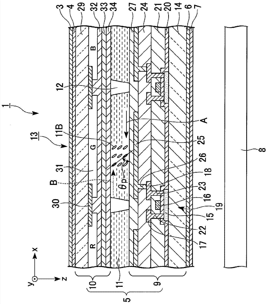
[0051] figure 1 It is a cross-sectional view showing the liquid crystal display device of this embodiment.
[0052] In addition, in each of the following drawings, in order to make each component easy to see, the scale of the size may be shown differently depending on the component.
[0053] The liquid crystal display device 1 of this embodiment is as figure 1 As shown, a liquid crystal panel 13 and a backlight source 8 are included. The liquid crystal panel 13 includes a first polarizing plate 3, a first retardation plate 4, a liquid crystal cell 5, a second retardation plate 6, and a second polarizing plate 7. The backlight source 8 is configured in figure 1 In the lower side of the liquid crystal panel 13. In the liquid c...
no. 2 approach
[0132] Below, use Figure 13 , Figure 14 The second embodiment of the present invention will be described.
[0133] The basic structure of the liquid crystal display device of this embodiment is the same as that of the first embodiment, and only the direction of the director of the liquid crystal molecules is different from that of the first embodiment.
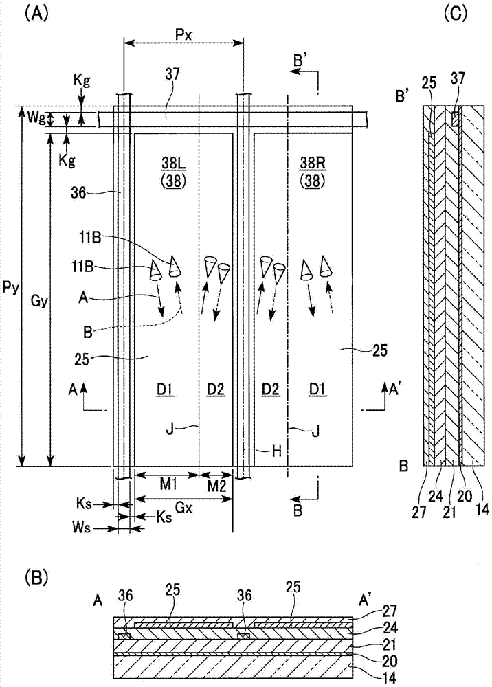
[0134] Figure 13 It is a plan view showing two adjacent sub-pixels in the liquid crystal display device of this embodiment. Figure 14 This is a diagram showing the simulation result of the alignment state of liquid crystal molecules when a voltage is applied to the liquid crystal display device of the present embodiment.
[0135] Figure 13 , Figure 14 Here, the same components as those in the drawings used in the first embodiment are given the same reference numerals, and detailed descriptions thereof are omitted.
[0136] In the case of the liquid crystal display device of this embodiment, as Figure 13 As shown, in the first do...
no. 3 approach
[0142] Below, use Figure 15 ~ Figure 17 The third embodiment of the present invention will be described.
[0143] The basic structure of the liquid crystal display device of this embodiment is the same as that of the first embodiment, and only the direction of the director of the liquid crystal molecules is different from that of the first embodiment.
[0144] Figure 15 It is a plan view showing two adjacent sub-pixels in the liquid crystal display device of this embodiment. Figure 16 It is a graph showing a simulation result of the alignment state of liquid crystal molecules when a voltage is applied in the liquid crystal display device of this embodiment. Figure 17 It is a plan view showing two adjacent sub-pixels in a liquid crystal display device according to a modification of this embodiment.
[0145] in Figure 15 ~ Figure 17 Here, the same components as those in the drawings used in the first embodiment are given the same reference numerals, and detailed descriptions thereo...
PUM
| Property | Measurement | Unit |
|---|---|---|
| angle | aaaaa | aaaaa |
| coating thickness | aaaaa | aaaaa |
| coating thickness | aaaaa | aaaaa |
Abstract
Description
Claims
Application Information
 - R&D
- Intellectual Property
- Life Sciences
- Materials
- Tech Scout
- Unparalleled Data Quality
- Higher Quality Content
- 60% Fewer Hallucinations
Browse by: Latest US Patents, China's latest patents, Technical Efficacy Thesaurus, Application Domain, Technology Topic, Popular Technical Reports.
© 2025 PatSnap. All rights reserved.Legal|Privacy policy|Modern Slavery Act Transparency Statement|Sitemap|About US| Contact US: help@patsnap.com