Circuit arrangement for inductively heating at least one fuel injector, fuel injector arrangement comprising the circuit arrangement, and method for operating the circuit arrangement and the fuel injector arrangement

A circuit device, fuel injection technology, applied in the direction of fuel injection device, valve heating/cooling device, fuel injection control, etc., to achieve the effect of saving lines, reducing costs, and avoiding sources

Active Publication Date: 2015-04-29
VTESCO TECH GMBH
View PDF5 Cites 0 Cited by
  • Summary
  • Abstract
  • Description
  • Claims
  • Application Information

AI Technical Summary

Problems solved by technology

[0010] Since the heater winding is connected to the power electronics via lead wires, the lead wires have to be designed with a correspondingly large cross-section, which in turn leads to additional costs

Method used


Image

  • Circuit arrangement for inductively heating at least one fuel injector, fuel injector arrangement comprising the circuit arrangement, and method for operating the circuit arrangement and the fuel injector arrangement
  • Circuit arrangement for inductively heating at least one fuel injector, fuel injector arrangement comprising the circuit arrangement, and method for operating the circuit arrangement and the fuel injector arrangement
  • Circuit arrangement for inductively heating at least one fuel injector, fuel injector arrangement comprising the circuit arrangement, and method for operating the circuit arrangement and the fuel injector arrangement

Examples


Embodiment Construction

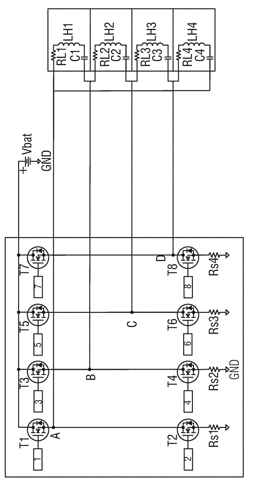
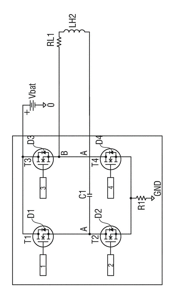
[0037] in accordance with figure 1 In the circuit arrangement of , a first series circuit is electrically connected between the positive pole Vbat and the negative pole GND of the voltage supply device, the first series circuit consisting of a first controllable switching element configured as a field effect transistor with a substrate diode D1 T1 is formed with a second controllable switching element T2, which is likewise designed as a field-effect transistor with a substrate diode D2. The connection point of the two switching elements T1 , T2 forms a first connection node A.

[0038] In the same way, between the positive pole Vbat and the negative pole GND of the voltage supply means is electrically connected a second series circuit consisting of a third controllable switching element T3 constructed as a field effect transistor with a substrate diode D3 and a fourth controllable switching element T4 configured as a field effect transistor with a substrate diode D4. The con...


PUM


Abstract

The invention relates to a circuit arrangement for inductively heating at least one fuel injector, comprising a power-transistor full-bridge circuit (T1, T2, T3, T4) which acts as a driver for operating a series resonant circuit (C1, LH1, RL1) at an alternating voltage at or near the resonant frequency. The series resonant circuit includes a heater coil on which the resulting voltage can be significantly higher than the supply voltage. The power that can be fed to the heater coil (LH1, RL1) can be modified or controlled by changing the frequency or the duty factor of the control signals of the switching elements of the bridge circuit.

Description

technical field [0001] The invention relates to a circuit arrangement for inductively heating at least one fuel injection valve, comprising: a first controllable switching element, which is connected between a positive pole of a supply voltage and a first connection node; a second controllable switching element, which The connection is between the first connection node and the negative pole of the supply voltage; the third controllable switching element is connected between the positive pole of the supply voltage and the second connection node; the fourth controllable switching element is connected between the second connection node and the negative pole of the supply voltage; and a first heater coil of at least one injection valve, said heater coil being electrically connected between the first and the second connection node. Background technique [0002] Such a full-bridge power output stage (also referred to as an H-bridge) realized by wiring four controllable switching e...

Claims


Application Information

Patent Timeline
IPC IPC(8): H05B6/06F02D41/20
CPCF02D41/20H05B6/06F02D2041/2006F02D2041/201F02D2041/2072F02D2041/2075F02M53/06F16K49/002
Inventor S. 博尔茨
Owner VTESCO TECH GMBH
Why Eureka
Try Eureka