Circuit arrangement for inductively heating at least one fuel injection valve as well as a fuel injection valve arrangement having such a circuit arrangement and method for operating the circuit arrangement and the fuel injection valve arrangement

A circuit device, fuel injection technology, applied in the direction of fuel injection device, valve heating/cooling device, fuel injection control, etc., to reduce costs, avoid sources, and save lines

Active Publication Date: 2017-09-01
VTESCO TECH GMBH
View PDF1 Cites 0 Cited by
  • Summary
  • Abstract
  • Description
  • Claims
  • Application Information

AI Technical Summary

Problems solved by technology

[0010] Since the heater winding is connected to the power electronics via lead wires, the lead wires have to be designed with a correspondingly large cross-section, which in turn leads to additional costs

Method used


Image

  • Circuit arrangement for inductively heating at least one fuel injection valve as well as a fuel injection valve arrangement having such a circuit arrangement and method for operating the circuit arrangement and the fuel injection valve arrangement
  • Circuit arrangement for inductively heating at least one fuel injection valve as well as a fuel injection valve arrangement having such a circuit arrangement and method for operating the circuit arrangement and the fuel injection valve arrangement
  • Circuit arrangement for inductively heating at least one fuel injection valve as well as a fuel injection valve arrangement having such a circuit arrangement and method for operating the circuit arrangement and the fuel injection valve arrangement

Examples


Embodiment Construction

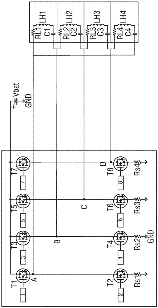
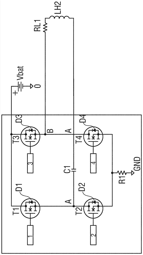
[0037] In accordance with figure 1 In the circuit device of the voltage supply device, a first series circuit is electrically connected between the positive electrode Vbat and the negative electrode GND of the voltage supply device, and the first series circuit consists of a first controllable switching element configured as a field effect transistor with a substrate diode D1 T1 is formed with a second controllable switching element T2 which is also configured as a field effect transistor with a substrate diode D2. The connection point of the two switching elements T1 and T2 forms a first connection node A.

[0038] In the same manner, a second series circuit is electrically connected between the positive pole Vbat and the negative pole GND of the voltage supply device, and the second series circuit consists of a third controllable switching element T3 configured as a field effect transistor with a substrate diode D3. And a fourth controllable switching element T4 configured as a...


PUM


Abstract

The invention relates to a circuit arrangement for inductively heating at least one fuel injection valve, said circuit arrangement having a full bridge circuit of power transistors (T1, T2, T3, T4) for use at or at a resonant frequency Nearby drivers that drive the series resonant circuit (C1, LH1, RL1) with an alternating voltage. The series resonant circuit includes a heater coil, where the resulting voltage at the heater coil can become significantly higher than the supply voltage. The power deliverable to the heater coils (LH1, RL1) can be varied and adjusted by changing the frequency or duty cycle of the control signal of the switching elements of the bridge circuit.

Description

Technical field [0001] The present invention relates to a circuit device for inductive heating of at least one fuel injection valve, which has: a first controllable switching element connected between the positive electrode of a supply voltage and a first connection node; and a second controllable switching element The connection is between the first connection node and the negative pole of the supply voltage; the third controllable switch element is wired between the positive pole of the supply voltage and the second connection node; the fourth controllable switch element is wired between the second connection node And the negative pole of the supply voltage; and the first heater coil of at least one injection valve, the heater coil is electrically connected between the first and second connection nodes. Background technique [0002] Such a full-bridge power final stage (also called H-bridge) realized by wiring four controllable switching elements is described in DE 34 15967 A1 ...

Claims


Application Information

Patent Timeline
Patent Type & Authority Patents(China)
IPC IPC(8): H05B6/06F02D41/20
CPCF02D41/20H05B6/06F02D2041/2006F02D2041/201F02D2041/2072F02D2041/2075F02M53/06F16K49/002
Inventor S.博尔茨
Owner VTESCO TECH GMBH
Why Eureka
Try Eureka