
Oil-water separation method and device

A technology of oil-water separation and oil drop, which is applied in separation methods, liquid separation, chemical instruments and methods, etc., can solve the problems of slow separation speed and achieve the effects of smooth slag discharge, reduced volume and improved efficiency

Inactive Publication Date: 2015-05-06
XIAN TECH UNIV
View PDF11 Cites 2 Cited by
  • Summary
  • Abstract
  • Description
  • Claims
  • Application Information

AI Technical Summary

Problems solved by technology

[0002] At present, the three-phase separators used in oilfields mainly include vertical three-phase separators and horizontal three-phase separators, while vertical separators mainly use methods such as cyclone separation and gravity separation. The phase separator separates the gas and liquid through the cyclone. After the oil and water enter the liquid collection area, the separation of the oil and water is mainly achieved by gravity sedimentation. Although the method of heating or adding a demulsifier is currently used to speed up the separation speed, these methods only start from To a certain extent, the separation effect is achieved, and it still takes a long time to separate oil and water, and the separation speed is slow

Method used


Image

  • Oil-water separation method and device
  • Oil-water separation method and device
  • Oil-water separation method and device

Examples


Embodiment Construction

[0020] The present invention will be described in further detail below in conjunction with the accompanying drawings and specific embodiments.

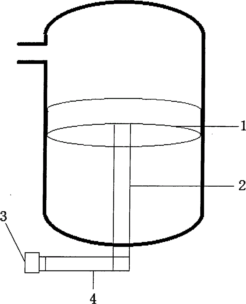
[0021] refer to figure 1 , a device used in the oil-water separation method, the vertical separator body is provided with a corrugated screen 1, the center of the corrugated screen 1 is connected to the lead screw 2, and the corrugated screen 1 is connected to the motor 3 through the transmission shaft 4.

[0022] The corrugated net plate 1 is circular and has a certain height. It is placed in a vertical separator. The center of the corrugated net plate 1 is connected to the lead screw 2. Driven by the motor 3, the transmission shaft 4 drives the lead screw 2 to rotate, and the lead screw 2 rotates. 2 drives the corrugated screen 1 to do compound motion.

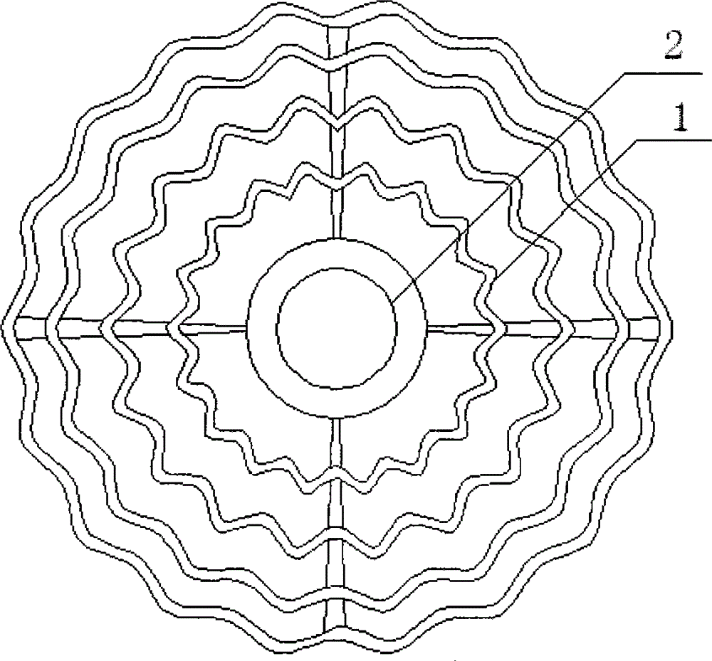
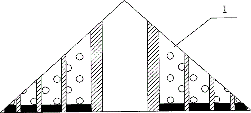
[0023] Such as Figure 2-Figure 4 As shown, the structure of the corrugated net plate is conical, concentric or involute.

[0024] Since the vertical separator is a cylindrical s...


PUM


Abstract

The invention discloses an oil-water separation method and an oil-water separation device. A corrugated sheet is driven by a motor to move up and down and rotate, and is driven by a moving shaft to do reciprocation; relative motion of liquid drops occurs through rotation motion of the corrugated sheet; the liquid drops in emulsion fluid with different heights are continuously conglomerated in an up-and-down motion process of the corrugated sheet; after the coagulation is carried out for a certain time, the separation between oil and water is completed; the corrugated sheet has certain length and width, and a zigzag channel for enabling the fluid to flow back and forth on the channel is provided, so that scattered liquid drops are conglomerated to a maximum extent; the corrugated sheet is made of hydrophilic materials, and is oleophylic and free of sticking oil; oil drops are adsorbed and are continuously conglomerated on the sheet, and after the oil drops are increased to a certain extent, the corrugated sheet moves to an oil layer and is blended into the oil after the oil drops are broken; through up-and-down motion and rotation motion, the oil drops are conglomerated during floating and float during coagulation; impurities glide by means of gravity, and a gap between stacked sheets is difficultly blocked.

Description

technical field [0001] The invention relates to an oil-water separation technology, in particular to an oil-water separation method and device. Background technique [0002] At present, the three-phase separators used in oilfields mainly include vertical three-phase separators and horizontal three-phase separators, while vertical separators mainly use methods such as cyclone separation and gravity separation. The phase separator separates the gas and liquid through the cyclone. After the oil and water enter the liquid collection area, the separation of the oil and water is mainly achieved by gravity sedimentation. Although the method of heating or adding a demulsifier is currently used to speed up the separation speed, these methods only start from To a certain extent, the separation effect has been achieved, but it still takes a long time to separate oil and water, and the separation speed is relatively slow. Contents of the invention [0003] In order to solve the short...

Claims


Application Information

Patent Timeline
Patent Type & Authority Applications(China)
IPC IPC(8): B01D17/02
CPCB01D17/0205
Inventor 来跃深齐忠霞张飞来浩李刚唐博田军委
Owner XIAN TECH UNIV
Learn More