Vertical dust remover

A dust collector and vertical technology, applied in chemical instruments and methods, dispersed particle separation, combined devices, etc., can solve the problems of short filter bag life, high operating costs and energy consumption, environmental pollution, etc., to achieve energy-saving treatment effects, reduce Floor space and investment costs, compact structure

Inactive Publication Date: 2015-05-06
HANGZHOU INST OF ADVANCED MATERIAL BEIJING UNIV OF CHEM TECH
View PDF4 Cites 10 Cited by
  • Summary
  • Abstract
  • Description
  • Claims
  • Application Information

AI Technical Summary

Problems solved by technology

At present, most of the traditional bag filter (collecting dust particles with a diameter larger than 10 μm) or filter element filter (collecting dust particles with a diameter larger than 5 μm) is used to filter the dusty gas, and then directly discharged, the discharged gas still accounts for about 100% of the total amount. About 5% of ultra-fine dust particles with a diameter of less than 5 μm cannot be removed, and these ultra-fine dust particles directly pollute the environment
Moreover, the disadvantages of the bag filter are also obvious. For example, the filter bag needs to be replaced frequently, and the life of the filter bag is also short. Especially under high temperature, corrosive environment and other working conditions, the filter bag is replaced more frequently, and the operating cost and Maintenance costs are more expensive
Another common dust removal method is wet dust removal, which uses spray to absorb liquid, and the liquid is in contact with dusty gas to achieve the purpose of absorption and purification. The disadvantages of wet dust removal are also obvious, such as the ability to absorb fine dust particles. Therefore, there is an urgent need in the market for a dust collector that can remove ultrafine dust particles with a diameter of less than 5 μm and relatively low energy consumption.

Method used


Image

  • Vertical dust remover

Examples


Embodiment Construction

[0015] The present invention will be further described below in conjunction with specific drawings and embodiments.

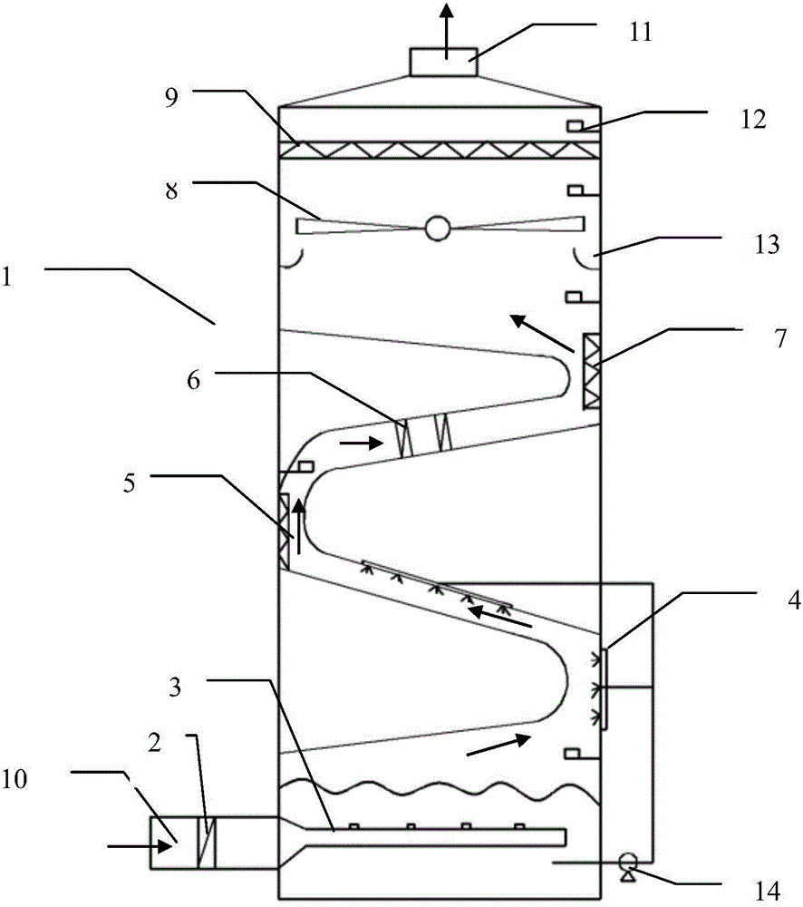
[0016] Such as figure 1 As shown, the flue gas dust removal device includes: a primary filter 2 located at the gas inlet 10, the gas inlet 10 is located at the bottom of the dust collector, and a gas distribution pan 3 at the bottom of the dust collector 1, and the gas distribution pan 3 communicates with the gas inlet 10 , the air distribution plate is submerged in the absorption liquid, and above the air distribution plate is a bent passage, and a sprinkler 4 is arranged at the first turning of the bent passage, and the sprayer 4 is connected with the circulating water pump 14 through a pipeline, and the circulating water pump 14 is connected to the bottom of the precipitator through pipes, an adsorption felt 5 is installed at the second turning, an electrostatic precipitator 7 is installed at the third turning, and a demisting device is installed in the chan...


PUM

PropertyMeasurementUnit
diameteraaaaaaaaaa

Abstract

The invention relates to a dust remover, and particularly relates to a wet and dry combined dust remover. The dust remover comprises a primary filter and a gas distributing disc 3, wherein the primary filter is positioned at the gas inlet; the gas distributing disc is positioned on the bottom of the dust remover; a bent channel is arranged above the gas distribution disc and comprises a first turning part, a second turning part and a third turning part; a centrifugal fan is arranged above the bent channel; the inner wall of the dust remover below the centrifugal fan is provided with a dust collecting groove; an HEPA filter screen is arranged above the centrifugal fan; a gas outlet is formed above the HEPA filter screen; the dust remover is internally provided with a particle concentration detector. The dust remover has the characteristics of high integration, low energy consumption and operation flexibility.

Description

technical field [0001] The invention relates to a dust removal device, in particular to a wet and dry combined dust removal device. It can remove ultra-fine dust particles in the dusty gas, and is especially suitable for dedusting the dusty gas, especially the fine dust gas. Background technique [0002] With the continuous enhancement of people's awareness of environmental protection, the requirements for the purification of dusty gas generated in the production process are also continuously improved. At present, most of the traditional bag filter (collecting dust particles with a diameter larger than 10 μm) or filter element filter (collecting dust particles with a diameter larger than 5 μm) is used to filter the dusty gas, and then directly discharged, the discharged gas still accounts for about 100% of the total amount. About 5% of ultra-fine dust particles with a diameter of less than 5 μm cannot be removed, and these ultra-fine dust particles directly pollute the envi...

Claims


Application Information

Patent Timeline
Patent Type & Authority Applications(China)
IPC IPC(8): B01D50/00B01D53/78
Inventor 吴浩
Owner HANGZHOU INST OF ADVANCED MATERIAL BEIJING UNIV OF CHEM TECH
Why Eureka
Try Eureka