Floating hydraulic clamping chuck for vehicle

A hydraulic clamping and chucking technology, used in chucks, turning equipment, machine drives, etc., can solve problems such as low efficiency, scrapped workpieces, and large labor, and achieve simple operation, fast clamping, and reduced labor. Effect

Inactive Publication Date: 2015-05-06
池州市维大茵特机械有限公司
View PDF8 Cites 9 Cited by
  • Summary
  • Abstract
  • Description
  • Claims
  • Application Information

AI Technical Summary

Problems solved by technology

[0003] The technical problem to be solved by the present invention is to provide a floating hydraulic clamping chuck for vehicles to solve the problems of heavy labor, extremely low efficiency and scrapped workpieces in the traditional clamping method

Method used


Image

  • Floating hydraulic clamping chuck for vehicle

Examples


Embodiment Construction

[0024] In the following, numerous specific details are set forth in order to provide a thorough understanding of the concepts underlying the described embodiments. It will be apparent, however, to one skilled in the art that the described embodiments may be practiced without some or all of these specific details. In other instances, well known processing steps have not been described in detail.

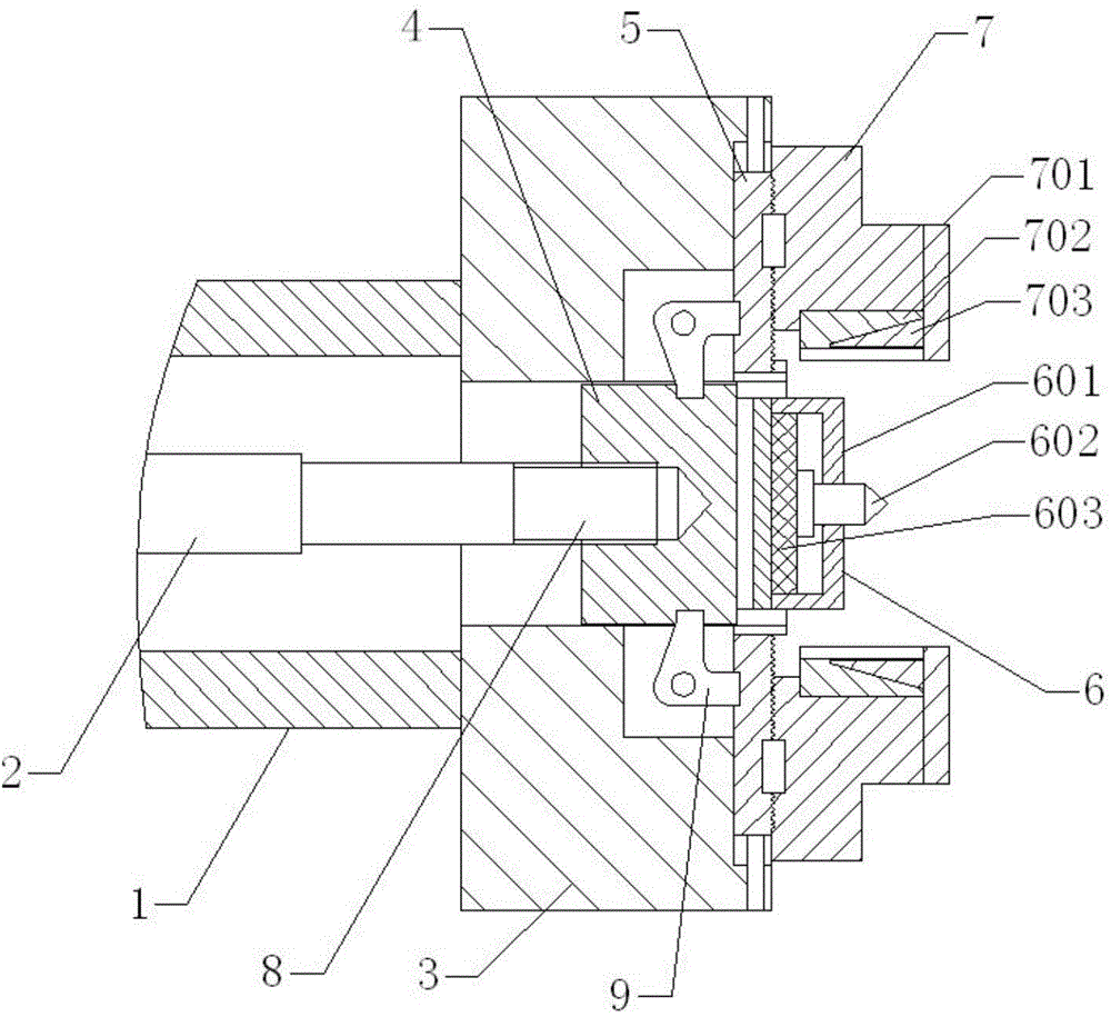
[0025] Such as figure 1 As shown, it includes spindle 1, machine pull rod 2, chuck seat 3, tension block 4, slider 5, floating center 6, claw 7, pull rod 8, lever 9, and chuck seat 3 is located at the center of the front end of spindle 1. The two are slip-fitted and connected with threads. The tensioning block 4 is located at the inner center of the chuck seat 3, and the two are movably connected. At the center of the front end of the disc seat 3, the two are connected by threads. The claw 7 is located at the center of the upper side of the front end of the chuck seat 3. The two are...


PUM


Abstract

The invention discloses a floating hydraulic clamping chuck for a vehicle. The floating hydraulic clamping chuck comprises a main shaft, a machine tool pull rod, a chuck seat, a tensioning block, a sliding block, a floating apex, a clamping claw, a pull rod and a lever, wherein the chuck seat is positioned at the center of the front end of the main shaft, and the chuck seat and the main shaft are in sliding fit and threaded connection; the tensioning block is positioned at the center in the chuck seat, and the tensioning block and the chuck seat are movably connected; the sliding block is positioned at the center of the upper side of the front end of the chuck seat, and the sliding block and the chuck seat are in threaded connection; the floating apex is positioned at the center of the front end of the chuck seat, and the floating apex and the chuck seat are in threaded connection; the clamping claw is positioned at the center of the upper side of the front end of the chuck seat, and the clamping claw and the chuck seat are in threaded connection; the pull rod is positioned at the center of the left end of the tensioning block, and the pull rod and the tensioning block are in threaded connection; the lever is positioned at the center of the upper side of the front end in the chuck seat, and the lever and the chuck seat are in threaded connection. The floating hydraulic clamping chuck is easy to operate, quick in clamping and high in precision; the work quantity is reduced, the production efficiency is improved, and scrapping of a workpiece is avoided.

Description

technical field [0001] The invention relates to a turning clamping device, in particular to a floating hydraulic clamping chuck for a vehicle. Background technique [0002] With the development of CNC lathes, CNC lathes have been widely used in the machining industry, but the clamping method is still the traditional manual chuck clamping. This clamping is to use a wrench to clamp and loosen the jaws, which requires a lot of labor. The efficiency is extremely low, and directly clamping on the blank surface is very easy to clamp the workpiece and cause scrapping. In view of the above defects, it is necessary to design a floating hydraulic clamping chuck for vehicles. Contents of the invention [0003] The technical problem to be solved by the present invention is to provide a floating hydraulic clamping chuck for vehicles to solve the problems of heavy labor, extremely low efficiency and scrapped workpieces in the traditional clamping method. [0004] In order to solve the ...

Claims


Application Information

Patent Timeline
IPC IPC(8): B23B31/30B23B23/04
CPCB23B23/04B23B31/302B23B2233/16B23B2233/32
Inventor 张启胜
Owner 池州市维大茵特机械有限公司
Why Eureka
Try Eureka