
Device for separating film on material tape

A separation device and material belt technology, which can be applied to layered products, lamination auxiliary operations, lamination, etc., can solve the problems of affecting production efficiency, inconvenience, time-consuming and laborious, etc., and achieve the effect of improving production efficiency and improving success rate.

Inactive Publication Date: 2015-05-06
马俊
View PDF6 Cites 1 Cited by
  • Summary
  • Abstract
  • Description
  • Claims
  • Application Information

AI Technical Summary

Problems solved by technology

The SMT tape is covered with a film, and in the production process of the SMT tape, the film needs to be peeled off. In the prior art, manual peeling is usually used, which is time-consuming, laborious, very inconvenient, and affects production efficiency.

Method used


Image

  • Device for separating film on material tape

Examples


Embodiment 1

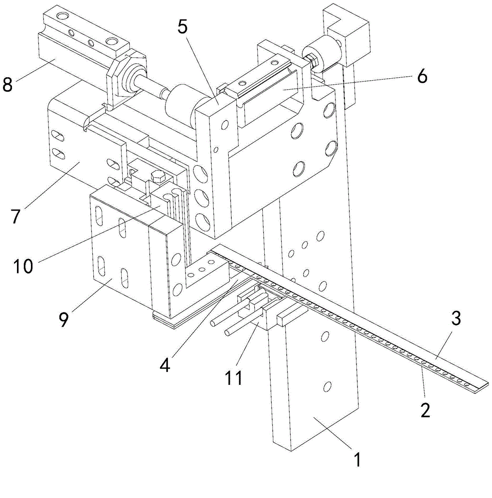
[0015] from the attached figure 1 It can be seen from the schematic diagram of the structure that this embodiment provides a material tape coating separation device, which includes a frame 1 and a support platform connected to the frame 1 for placing the material tape 2 (not shown in the accompanying drawings). ), a stripper 4 movably arranged on the frame 1 , a driving device for driving the stripper 4 to move, and the frame 1 is also provided with a heating device 11 for heating the material tape 2 . The material tape coating separation device of the present invention, by moving the peeler 4, presses it on the material tape 2 and inserts it between the material tape 2 and the film 3, so as to peel off the film 3, and by heating the material tape 2 (and covering the film 3) The film 3) on the top can be more convenient and stable to facilitate the insertion of the peeler 4.

[0016] The stripper 4 in this embodiment is a thin blade.

[0017] The frame 1 is provided w...

Embodiment 2

[0028] The only difference between this embodiment and the first embodiment is that the supporting platform is arranged on the bracket 1 so as to be movable left and right, and the bracket 1 is further provided with a fourth driving device for driving the supporting platform to move.

[0029] The working steps of the material tape coating separation device in this embodiment:

[0030] Steps 1-4 are the same as in Embodiment 1;

[0031] Step 5. After the stripper 4 is inserted between the material belt 2 and the film 3, the support platform is moved along the length direction of the material belt 2 by moving the support platform, so that the material belt 2 and the film 3 are separated.

Embodiment 3

[0033] The only difference between this embodiment and the second embodiment is that the stripper 4 is fixedly connected to the third connecting frame 9 , and the third connecting frame 9 is directly connected to the first connecting frame 5 so as to be movable up and down. The third driving device 10 is arranged on the first connecting frame 5 .

[0034] The working steps of the material tape coating separation device in this embodiment:

[0035] Step 1. Position the stripper 4 at the initial position at the start of the work by moving the first connecting frame 5;

[0036] Steps 2-5 are the same as the second embodiment.


PUM


Abstract

The invention discloses a device for separating a film on a material tape. The device comprises a rack, a supporting platform, strippers and driving devices, wherein the supporting platform is connected on the rack and is used for placing a material tape; the strippers are movably arranged on the rack; the driving devices are used for driving the strippers to move; a heating device used for heating the material tape is also arranged on the rack. The device can be used for automatically stripping the film covering the material tape, thus greatly improving the production efficiency and the success rate. The device is not limited to separation of films on SMT (surface mounted technology) material tapes and can be also applied to separation of films on other material tapes in actual production.

Description

technical field [0001] The invention relates to a strip-coated film separating device, in particular to an SMT strip-coated film separating device. Background technique [0002] It is surface mount technology (Surface Mount Technology) (abbreviation of Surface Mounted Technology), an electronic assembly technology and the most popular technology and process in the electronic assembly industry. It is the electronic components, such as resistors, capacitors , Transistors, integrated circuits, etc. are mounted on a printed circuit board and electrically connected by soldering. The SMT tape is covered with a film, and in the production process of the SMT tape, the film needs to be peeled off. In the prior art, manual peeling is usually used, which is time-consuming, laborious, very inconvenient, and affects production efficiency. Contents of the invention [0003] In order to solve the above problems, the object of the present invention is to provide a strip-coated film separ...

Claims


Application Information

Patent Timeline
IPC IPC(8): B32B38/10
CPCB32B38/10
Inventor 马俊
Owner 马俊
Features
  • Generate Ideas
  • Intellectual Property
  • Life Sciences
  • Materials
  • Tech Scout
  • Unparalleled Data Quality
  • Higher Quality Content
  • 60% Fewer Hallucinations
Learn More