
Protective device for vehicle transmission shaft

A protection device and transmission shaft technology, applied in control devices, vehicle parts, transportation and packaging, etc., can solve the problems of reducing the shaking amplitude of the transmission shaft, the shaking of the transmission shaft, etc., to improve the safety performance, realize fixing and disassembly, prevent mopping effect

Active Publication Date: 2015-05-06
BEIQI FOTON MOTOR CO LTD
View PDF8 Cites 1 Cited by
  • Summary
  • Abstract
  • Description
  • Claims
  • Application Information

AI Technical Summary

Problems solved by technology

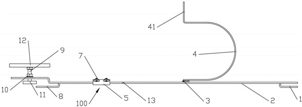
[0008] The purpose of the present invention is to provide a protective device for the transmission shaft of a vehicle that can fix the transmission shaft to the vehicle frame during the installation process and reduce the sloshing range of the transmission shaft, and solve the problem that the transmission shaft in the prior art uses ropes along the longitudinal direction. The problem of sloshing in the longitudinal direction of the beam

Method used


Image

  • Protective device for vehicle transmission shaft
  • Protective device for vehicle transmission shaft
  • Protective device for vehicle transmission shaft

Examples


Embodiment 1

[0041] Such as Figures 1 to 6 As shown, the present invention is used for the protective device of the propeller shaft of vehicle, and it comprises: protective beam 2 and protective ring 4, and the two ends of protective beam 2 are respectively provided with the first connection part that is used for detachable connection with the vehicle frame of vehicle and the second connection part. Preferably, the first connecting part includes a first U-shaped groove 1 fixed at the end of the protective beam 2 and opening outward, and the second fixing part includes a second U-shaped groove 1 fixed at the end of the protective beam 2 and opening outward. The slot 8, the first U-shaped slot 1 and the second U-shaped slot 8 are respectively used to engage with the beam of the vehicle frame. The protective ring 4 is provided with an opening, and the protective ring 4 is preferably a U-shaped, oval or circular steel ring, and the size of the protective ring 4 is adapted to the transmission...

Embodiment 2

[0048] Embodiment 2 is basically the same as Embodiment 1, except that the insertion slot 100 is replaced by an integrated bushing with a cross-section of a zigzag shape, and the insertion slot 100 of the integrated sleeve is not provided with a locking portion 14 . During use, the slot 100 is slid to be connected to the plug board 41, lacking the locking function of the locking part 14 and the locking slot 13, and compared with Embodiment 1, the slot cannot be prevented from being locked during use. move.

Embodiment 3

[0050] This embodiment is basically the same as Embodiments 1 and 2, except that the first connecting portion and the second connecting portion at both ends of the protection beam 2 are detachably connected to the longitudinal beam of the vehicle frame by fasteners. During use, the two ends of the protection beam are clamped to the longitudinal beam of the vehicle frame through fasteners, and the protection ring is rotated to fix the position of the transmission shaft.


PUM


Abstract

The invention relates to the field of automobile assembling, and discloses a protective device for a vehicle transmission shaft and suitable for a production line. The protective device comprises a protective beam and a protective ring. The two ends of the protective beam are provided with a first connection portion and a second connection portion which are used for being detachably connected with a vehicle frame of a vehicle. The protective ring is provided with an opening. One end of the opening of the protective ring is hinged to the protective beam. The other end of the opening of the protective ring is provided with a third connection portion for being detachably connected with the protective beam. The protective device is simple in structure and convenient to use. According to the protective device, the protective beam is arranged on the vehicle frame through the first connection portion and the second connection portion at the two ends of the protective beam, and the transmission shaft is fixed in the protective ring, limited effectively in the assembling process and prevented from generating large-range shaking; meanwhile, compared with a rope blinding mode in the prior art, the protective device has the advantages of preventing the transmission shaft from swinging along a longitudinal beam of the vehicle frame in the longitudinal direction.

Description

technical field [0001] The invention relates to the field of automobile devices, in particular to a protection device for a transmission shaft of a vehicle that can prevent the transmission shaft from shaking. Background technique [0002] For rear-wheel drive or four-wheel drive vehicles, the transmission shaft is an important part of its power transmission, and its performance directly affects the performance and life of the vehicle. Therefore, during the assembly process, the protection of the transmission shaft must be done well. At present, on the production line, the assembly process of the transmission shaft mainly has the following two methods: [0003] Method 1: First place the frame with the reverse side upwards, install the rear axle, fix the transmission shaft and rear axle connection flange, connect the intermediate support, then turn the frame over, install the engine and transmission, and fix the transmission shaft and transmission connection flange , fixed ...

Claims


Application Information

Patent Timeline
Patent Type & Authority Applications(China)
IPC IPC(8): B60K17/22
Inventor 郭凤刚赵建慧韩云肖徐伟
Owner BEIQI FOTON MOTOR CO LTD
Learn More