Multi-working-condition auxiliary boom structure and crane using same

A multi-working condition, crane technology, applied in the direction of cranes, etc., can solve the problems of inflexibility, affecting the performance of the whole vehicle, increasing the section of the lengthened section, etc., to achieve the effect of increasing flexibility and wide product adaptability

Active Publication Date: 2015-05-06
XUZHOU HEAVY MASCH CO LTD
View PDF4 Cites 9 Cited by
  • Summary
  • Abstract
  • Description
  • Claims
  • Application Information

AI Technical Summary

Problems solved by technology

At present, the truss arm in the industry has two ways of angle transformation: fixed value angle and stepless amplitude change. The variable angle rotation point is designed at the connection between the connecting frame and the rotating frame or the basic jib. The relative distance between the rotation point and the main boom head is fixed. When the floor height is higher than the rotation point during construction, the truss arm will not be able to adjust the angle, such as image 3 As shown, the current solution to this problem is to increase the length of the boom system in front of the swivel frame 13 on the basis of the existing truss arm form, that is, to increase the cross-sectional size of the extension section 2, and then move the installation position forward to make the rotation point relatively backward. To achieve the purpose of extending the working range of the boom system, its working range is as follows: Figure 4 As shown (in order to simply analyze the jib to make the problem clear, here it is assumed that t

Method used


Image

  • Multi-working-condition auxiliary boom structure and crane using same
  • Multi-working-condition auxiliary boom structure and crane using same
  • Multi-working-condition auxiliary boom structure and crane using same

Examples


Embodiment Construction

[0028] In order to enable those skilled in the art to better understand the solution of the present invention, the present invention will be further described in detail below in conjunction with the accompanying drawings and specific embodiments.

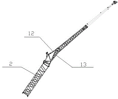
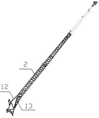
[0029] Such as Figure 5 As shown, the multi-working condition jib structure of the present invention includes a boom, a first luffing mechanism 1 for changing the working angle of the jib, and an extension section 2 for increasing the length of the jib, and the extension section 2 is installed on The front end of the first luffing mechanism 1, the extension section 2 at the front end of the first luffing mechanism 1 is provided with the second luffing mechanism 3, on the basis of the original jib structure, the second luffing mechanism 3 is added, so that the original jib A rotation point is added to the front section of the system, which increases the flexibility of boom angle transformation and working condition selection.

[00...


PUM


Abstract

The invention discloses a multi-working-condition auxiliary boom structure which comprises a boom rest, a first jib luffing mechanism (1) used for converting a working angle of an auxiliary boom, and an lengthened section (2) used for increasing the length of the boom rack, wherein the lengthened section is mounted at the front end of the first jib luffing mechanism, and a second jib luffing mechanism (3) is arranged on the boom rest at the front end of the first jib luffing mechanism. The invention further provides a crane with the multi-working condition auxiliary boom structure. The auxiliary boom mechanism is detachably connected to a hoisting boom of the crane. According to the multi-working-condition auxiliary boom structure, on the basis of an original boom rest structure, the second jib luffing mechanism is additionally provided, so that a rotary point is additionally arranged at the front section of an original boom rest system, so that the flexibility of converting the boom rest angle and selecting a working condition is increased; the original boom rack structure is not changed, a newly-designed rotary device is used as an option configuration, without influencing the constitution of the original boom rest structure; the rotary device can be assembled on multiple positions of the boom rest system, so that the flexibility of converting the boom rest angle and selecting the working condition is increased, and the product applicability is relatively wide.

Description

technical field [0001] The invention relates to a crane, in particular to a multi-working-condition jib structure and a crane using the structure. Background technique [0002] Cranes are widely used in the field of engineering machinery technology. The crane lifts heavy objects through the boom and the wire rope wound around the main pulley of the boom. Depending on the lifting needs, the jib of a crane usually has a main jib and a jib. Such as figure 1 As shown, the auxiliary jib is a truss arm structure installed at the end of the main jib. The angle change is mainly completed by the combination of the swivel frame 13 and the pull plate 12. The length is adjusted by increasing or decreasing the extension joint 2, which is used to expand the working range of the jib system. , to increase the lifting height of the vehicle. Thus, in figure 1 Under this structure, the working range that can be realized according to the length of the extension section 2 is also different, ...

Claims


Application Information

Patent Timeline
IPC IPC(8): B66C23/70B66C23/82
CPCB66C23/70B66C23/82
Inventor 李小燕陈志灿李凯
Owner XUZHOU HEAVY MASCH CO LTD
Why Eureka
Try Eureka