Ticket gate device

A technology of turnstiles and restricting devices, applied to roads, restricted traffic, roads, etc., can solve problems such as difficult passage, impact of crutches, complex structure, etc., and achieve the effects of ensuring safety, improving safety, and being easy to control

Inactive Publication Date: 2015-05-06
SICHUAN APOCO TECH
View PDF8 Cites 1 Cited by
  • Summary
  • Abstract
  • Description
  • Claims
  • Application Information

AI Technical Summary

Problems solved by technology

[0003] Most of the existing turnstiles adopt the turntable type for many times, and three brake levers are used to rotate to realize the release of people. However, the turnstiles using this structure, such as the "gate" with the authorization announcement number CN2895687 Y, not only have a complicated structure, but also When one of the brake levers is rotating, the other brake lever is also turned, which is not conducive to the passage of people with disabilities, such as people in wheelchairs and people on crutches.
During the rotation of the three gate levers, the wheelchair is bulky and difficult to pass through; and during the rotation of the gate, it is easy to affect the crutches, making it difficult to move the crutches, posing a threat to the safety of passers-by

Method used


Image

  • Ticket gate device
  • Ticket gate device

Examples


Embodiment 1

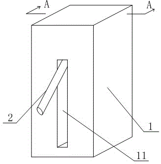
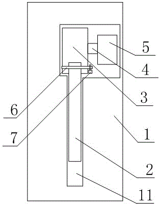
[0022] like figure 1 and figure 2 The gate device shown includes a gate housing 1, the gate housing 1 is provided with a brake rod 2, the gate housing 1 is provided with a brake rod rotation groove 11, and the brake rod 2 is located in the brake lever rotation groove 11, the brake lever control device is arranged in the gate housing 1, and the brake lever control device includes a rotating wheel 3, a connecting shaft 4 for driving the rotating wheel 3 to rotate, and a The driving device 5 that drives the connecting shaft 4 to rotate. The driving device can adopt a motor.

[0023] The direction of rotation of the brake lever can be horizontal rotation or vertical rotation. As the best rotation direction, it can be rotated in the horizontal plane, and the rotation direction is to rotate in the forward direction of traffic. That is, the position of the brake lever rotating groove 11 can be horizontal or vertical.

Embodiment 2

[0025] like figure 1 and figure 2 The gate device shown in this embodiment is refined on the basis of the above embodiments, that is, the gate housing 1 is provided with a rotation angle limiting device. The rotation angle of the brake lever is preferably 90 degrees. When the brake lever is perpendicular to the channel, it can restrict the passage of personnel, and when it is rotated 90 degrees, the brake lever can be attached to the gate casing, so as not to affect the passage of personnel. The rotation angle limiting device is used to limit the rotation angle of the brake rod, so as to avoid the excessive rotation angle of the brake rod and affect the time to return to the original state. The original state is the state where the brake lever is perpendicular to the channel.

[0026] The rotation angle limiting device includes a limiting groove arranged in the gate housing 1 and a limiting rod fixed on the rotating wheel 3 to limit the rotating angle of the rotating wheel...

Embodiment 3

[0028] like figure 1 and figure 2 The gate device shown in this embodiment is optimized on the basis of the above embodiments, that is, the gate lever 2 is fixedly connected to the rotating wheel 3 through threads.

[0029] A locking device is provided between the rotating wheel 3 and the brake lever 2 .

[0030] The locking device is a locking lever 6 inserted between the rotating wheel 3 and the brake lever 2 and a switch lock 7 fixed at one end of the locking lever 6 .

[0031] The brake lever 2 is easily damaged and needs to be replaced. The brake lever and the rotating wheel are connected by threads, which facilitates the replacement of the brake lever. However, by adopting the threaded connection mode, personnel can easily remove the brake lever, so that the gate device can perform channel management functions, and the lock lever and the rotating wheel are reinforced by the locking device to enhance the safety of the brake lever. The staff have the authority to open...


PUM


Abstract

The invention discloses a ticket gate device. The ticket gate device comprises a ticket gate shell. A gate bar is arranged in the ticket gate shell. A gate bar rotating groove is formed in the ticket gate shell. The gate bar is located in the gate bar rotating groove. A gate bar controlling device is arranged in the ticket gate shell. The gate bar controlling device comprises a rotating wheel, a connecting shaft and a driving device, wherein the connecting shaft is used for driving the rotating wheel to rotate, and the driving device is used for driving the connecting shaft to rotate. The ticket gate device is simple in structure, and people can conveniently pass through the ticket gate device.

Description

technical field [0001] The invention relates to the field of channel management equipment, in particular to a gate device. Background technique [0002] The gate is a kind of channel management equipment, which is used to manage the flow of people and regulate the entry and exit of pedestrians. It is mainly used in the subway gate system and the toll ticket gate system. Its most basic and core function is to realize that only one person can pass through at a time, and it can be used at the entrance of various charging and access control occasions. [0003] Most of the existing turnstiles adopt the turntable type for many times, and three brake levers are used to rotate to realize the release of people. However, the turnstiles using this structure, such as the "gate" with the authorization announcement number CN2895687 Y, not only have a complicated structure, but also When one of the brake levers rotates, the other brake lever also rotates thereupon, which is not conducive ...

Claims


Application Information

Patent Timeline
IPC IPC(8): E01F13/06
CPCE01F13/06
Inventor 赖启天
Owner SICHUAN APOCO TECH
Why Eureka
Try Eureka