Slide valve

A sliding valve and spool technology, applied in sliding valves, multi-way valves, valve devices, etc., can solve the problems of rising material costs and manufacturing costs, and achieve the effect of simple structure and restraining the rise of manufacturing costs

Active Publication Date: 2015-05-06
SAGINOMIYA SEISAKUSHO INC
View PDF6 Cites 8 Cited by
  • Summary
  • Abstract
  • Description
  • Claims
  • Application Information

AI Technical Summary

Problems solved by technology

However, in the above-mentioned countermeasures, it is not preferable to simply increase the material cost and the manufacturing cost.

Method used


Image

  • Slide valve
  • Slide valve
  • Slide valve

Examples


Embodiment Construction

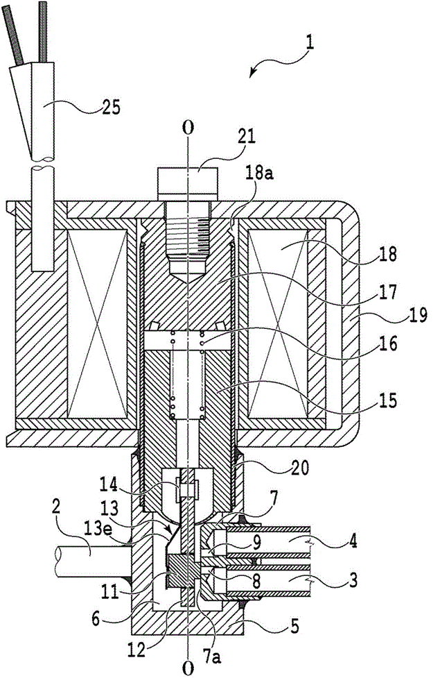
[0030] figure 1 A cross-sectional view of a typical embodiment of the slide valve of the present invention is shown. As an embodiment of the present invention, figure 1 The shown slide valve is an example of a three-way valve used in an automatic vending machine, but the present invention is not limited thereto, and can also be applied to a slide valve as a four-way valve incorporated in an air conditioner, a refrigerator, etc. as described later. .

[0031] The slide valve 1 of this embodiment has figure 1 The center axis O-O extending vertically in the vertical direction roughly includes a valve main body 5 , a valve element assembly 10 , and a solenoid 18 .

[0032]The valve main body 5 constituting the slide valve 1 defines a valve chamber 6, which is connected to the inlet side joint 2 communicating with the upstream side channel through the inlet side port (not shown), and connected to the outlet side port 8 and 9 through the outlet side port. The outlet-side joints ...


PUM


Abstract

The invention provides a slide valve preventing inclination in back pressure in a simple construction. The slide valve at least has a valve main body drawing out a valve body having an inlet side port in an opening; a valve seat configured to be in the valve body and having at least one outlet side port, relative to a valve body opening, in a valve body surface; and a valve core assembly at least comprising a plunger driven by a solenoid and a connection rod, a valve core and a leaf spring assembled on the plunger in an integrated mode. The slide valve opens and closes the outlet side port. The valve core is maintained to be at the connection rod, opens and closes at least one outlet side port and slides on a valve seat surface of a valve seat. The valve core also has a sealing surface opening and closing the outlet side portion and a back surface opposite to the sealing surface. The leaf spring is abutted against the back surface of valve core and presses the valve core on the valve seat surface of the valve seat. A protrusion forms on the leaf spring. A step portion comprising a bottom surface abutted against the protrusion forming on the leaf spring forms on the back surface of the valve core.

Description

technical field [0001] The present invention relates to a slide valve incorporated in an air conditioner, an automatic vending machine, a refrigerator, etc., to control the flow of a fluid such as a refrigerant. Background technique [0002] In air conditioners, vending machines, and refrigerators, conventionally, a so-called three-way valve is used in which a valve element slides on a valve seat surface to open, close or switch a plurality of outlet-side ports formed on the valve seat. Or a slide valve for a four-way valve. [0003] For example, in a slide valve as a three-way valve disclosed in Patent Document 1, the valve element constituting the slide valve is driven via a plunger magnetically attracted by a solenoid, and slides reciprocatingly on a valve seat surface. The two outlet side ports are opened and closed. Specifically, the spool of the slide valve is inserted into a through hole formed at the tip end of the connecting rod fixed to the plunger. In addition,...

Claims


Application Information

Patent Timeline
Patent Type & Authority Applications(China)
IPC IPC(8): F16K3/314
CPCF16K3/314F16K11/0655
Inventor 熊田和彦入子隆之三留陵
Owner SAGINOMIYA SEISAKUSHO INC
Why Eureka
Try Eureka