Lattice structure tester probe bay protection structure

A lattice structure and protection structure technology, applied in the field of lattice structure testing machine probe socket protection structure, can solve the problems of adsorption of debris, easy residue, damage, etc., to maintain the shape and service life, prevent The effect of chemical corrosion and cable damage prevention

Inactive Publication Date: 2015-05-06
SUZHOU ZZH INTPROP SERVICES
7 Cites 2 Cited by

AI-Extracted Technical Summary

Problems solved by technology

[0002] The dot-matrix structure is the key component to realize the patterned fireworks. It determines whether the display of the fireworks can achieve the effect required by the user. It is also a key component that determines whether the patterned fireworks can be miniaturized and integrated. The volume of the dot-matrix structure , Dot matrix density, molding efficiency, production cost and post-processing steps all seriously restrict the overall cost, safety, reliability and production efficiency of patterned fireworks. The dot matrix structure requires precision molds, precision molding, and a large number of precision Post-processing tools, quality inspection tools, shaping tools, filling tools, and anti-mistake and anti-explosion measures, etc., the core components of patterned fireworks require a large number of high-tech support across industries and technical fields and original innovations that dare to pioneer and experiment spirit, the current indust...

Method used

The test probe 12 is inserted in the socket insertion groove 2 of the socket body 1, because the angle between the busbar on the surface of the socket guide vertebral platform groove 5 and the axis of rotation is 15-35°, it is easy to directly insert it into the bottom , limited by the probe holder 6, the test probe 12 is partially fixed, but other parts are suspended in the air. Since the probe head avoidance groove 7 and the metal collar 8 are all through holes, residual liquid cannot be a...

Abstract

The invention discloses a lattice structure tester probe bay protection structure. The protection structure comprises a bay body, the body comprising a bay insertion slot, the body attachment and the cable around the hook portion, the insertion slot is located in bay central body, the insert holder into the slot comprises an upper frame guide the probe tip is inserted vertebral station slot, the middle and lower part of the escape groove metal rings connected in turn, the lattice structure of the test probe tester is inserted into the slot in the bay, test probe cable or wire in the cable can be wrapped or wrapped around the hook portion. The invention is capable of full-lattice structure to protect the fragile tester probes, including the prevention of collision, hit, rub, plug and other mechanical damage, to prevent the probe cable damage, to prevent the probe chemical corrosion, prevent galvanic corrosion probe substantially maintain the shape and the life of the probe.

Application Domain

Electrical measurement instrument detailsElectrical testing

Technology Topic

Wrap aroundTest probe +2

Image

  • Lattice structure tester probe bay protection structure
  • Lattice structure tester probe bay protection structure
  • Lattice structure tester probe bay protection structure

Examples

  • Experimental program(1)

Example Embodiment

[0022] The present invention will be described in detail below with reference to the accompanying drawings and in combination with embodiments.
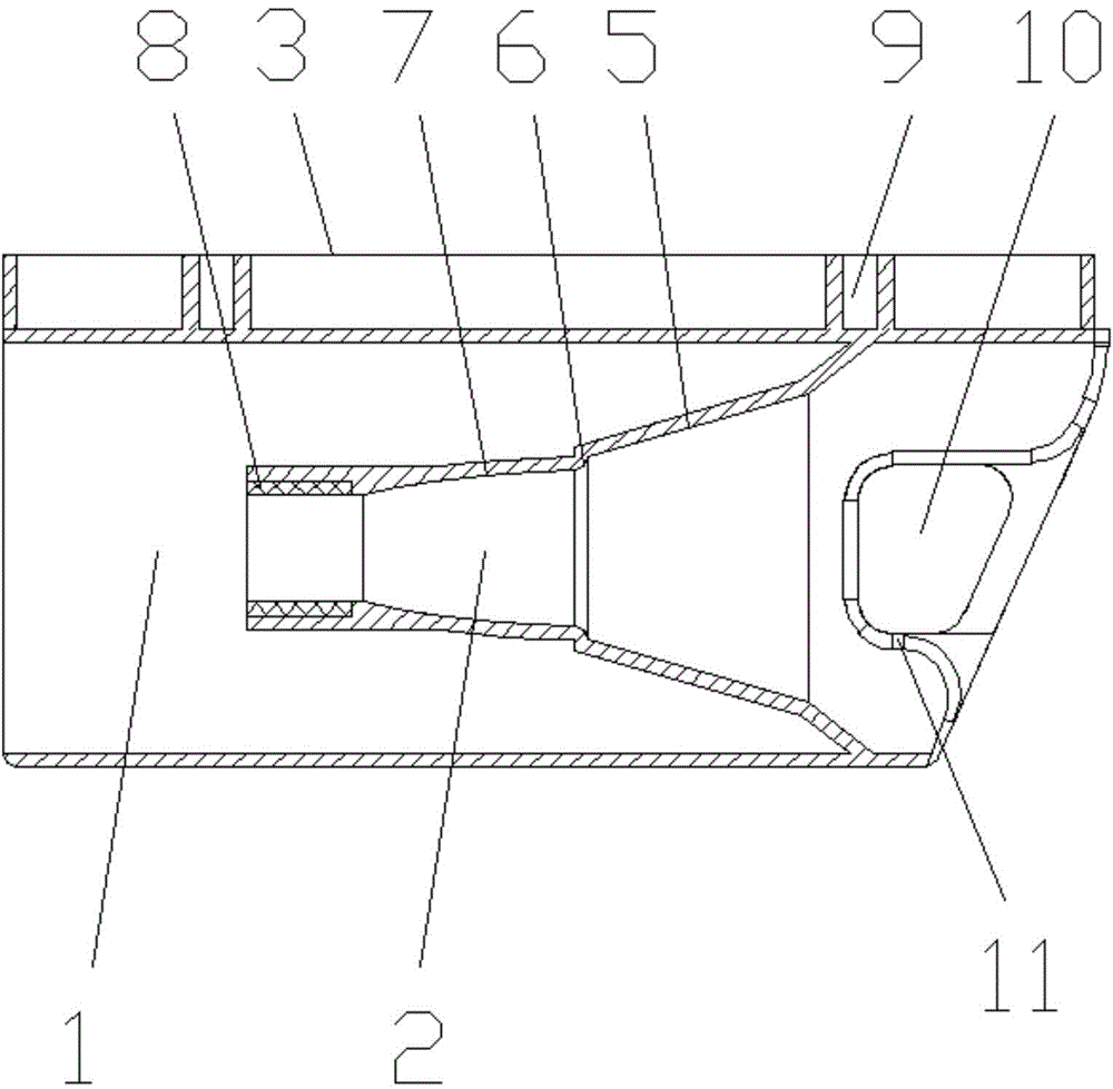
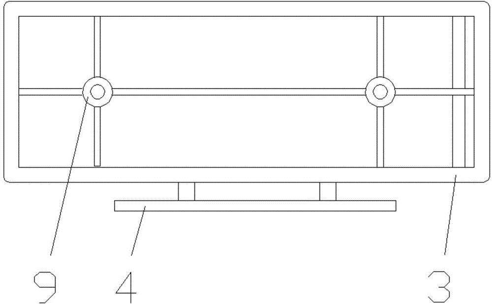
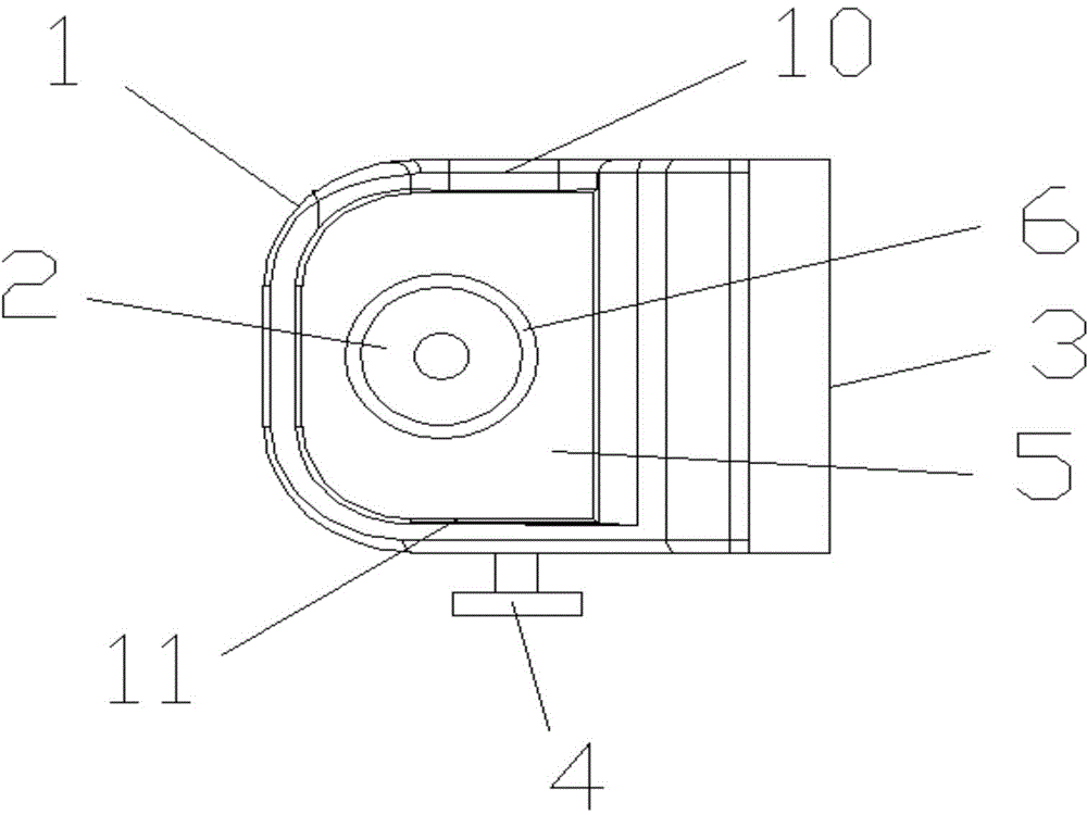
[0023] refer to Figure 1-Figure 6 As shown, the lattice structure testing machine probe socket protection structure includes a socket body 1, and the socket body 1 includes a socket insertion slot 2, a body installation part 3 and a cable hanging part 4. The rack insertion slot 2 is located in the middle of the rack body 1, and the rack insertion slot 2 includes the upper rack guiding vertebral groove 5, the middle probe head avoidance slot 7 and the lower metal collar 8 connected in sequence, The test probe 12 of the lattice structure testing machine is inserted into the insertion slot 2 of the socket, and the cables or lead wires of the test probe can be wound or hung on the cable hanging part 4 .
[0024] Further, the body installation part 3 is provided with a connecting screw hole post 9 and a reinforcing rib group.
[0025] Further, a U-shaped open window 11 and a closed through-hole window 10 are respectively provided on both sides of the upper part of the socket body 1 .
[0026] Further, a probe holder 6 is provided between the guide frame groove 5 and the probe head escape groove 7, and the included angle between the generatrix on the surface of the guide frame groove 5 and the rotation axis is 15°. -35°.
[0027] Further, the avoidance groove 7 of the probe head is in clearance fit with the test probe 12, and the clearance size is 0.25-2 mm.
[0028] Further, the surface of the metal collar 8 is plated with silver, and the thickness of the silver plate is 12-25 μm. The working principle of this embodiment is as follows:
[0029] Insert the test probe 12 into the socket insertion groove 2 of the socket body 1, because the included angle between the generatrix on the surface of the socket guiding vertebral groove 5 and the rotation axis is 15-35°, it is easy to insert directly to the bottom, and the probe The needle support table 6 is limited, and the test probe 12 is partially fixed, but other parts are suspended in the air. Since the avoidance groove 7 of the probe head and the metal collar 8 are both through holes, residual liquid cannot be accommodated, and the metal collar 8 has a silver coating. The layer itself is not easy to rust, and it does not absorb substances that can damage the test probe 12. The head of the test probe 12 is well protected. After the test probe 12 is inserted, straighten the connection lines behind the test probe 12 Cable, use U-shaped open window 11, closed through-hole window 10 and cable hanging part 4 to protect and fix the connection cable to prevent unnecessary damage to the connection cable.
[0030] The above descriptions are only preferred embodiments of the present invention, and are not intended to limit the present invention. For those skilled in the art, the present invention may have various modifications and changes. Any modifications, equivalent replacements, improvements, etc. made within the spirit and principles of the present invention shall be included within the protection scope of the present invention.

PUM

PropertyMeasurementUnit
Thickness12.0 ~ 25.0µm

Description & Claims & Application Information

We can also present the details of the Description, Claims and Application information to help users get a comprehensive understanding of the technical details of the patent, such as background art, summary of invention, brief description of drawings, description of embodiments, and other original content. On the other hand, users can also determine the specific scope of protection of the technology through the list of claims; as well as understand the changes in the life cycle of the technology with the presentation of the patent timeline. Login to view more.

Similar technology patents

Cable straightening equipment for municipal engineering

InactiveCN109773084AAvoid cable damageSolve the single function
Owner:上海锦屹通信工程有限公司

Method for producing concentrated nitric acid storage tank by winding carbon fibers

InactiveCN105936389AOptimizing the winding angleAvoid Galvanic Corrosion
Owner:中国石油集团东北炼化工程有限公司 +1

Classification and recommendation of technical efficacy words

  • Avoid cable damage

Cable straightening equipment for municipal engineering

InactiveCN109773084AAvoid cable damageSolve the single function
Owner:上海锦屹通信工程有限公司
Why Eureka
Try Eureka