Method for high-speed rotation laser direct-writing arbitrary graph

A technology of laser direct writing and high-speed rotation, applied in the field of high-speed rotating laser direct writing of arbitrary graphics and laser direct writing, it can solve the problems of difficult to guarantee accuracy, inability to write graphics, and inability to write, and achieve the effect of wide application prospects.

Active Publication Date: 2015-05-06
杭州光学精密机械研究所
View PDF7 Cites 8 Cited by
  • Summary
  • Abstract
  • Description
  • Claims
  • Application Information

AI Technical Summary

Problems solved by technology

Cartesian coordinate system direct writing system is suitable for processing rectangular orthogonal devices (such as semiconductor chips), but it has a great disadvantage in processing micro-nano devices with circular pattern distribution. It can only be spliced ​​block by block, and the accuracy is difficult to obtain. Guaranteed; Polar coordinate system direct writing system has natural advantages in processing circular micro-nano components (such as circular gratings, Fresnel lenses), without splicing, and can seamlessly and coherently complete large-format patterns during the high-speed rotation of the translation stage writing of
[0003] In the previous technology, the State Key Laboratory of Modern Optical Instruments of Zhejiang University used a full-digital turntable to realize the writing of polar coordinate graphics (Liang Yiyong, full-digital laser direct writing turntable system, Optoelectronic Engineering, Volume 31, Issue 5, 2004). The generator unit can only emit laser intensity modulation signals at a specific position on the rotary table, so it can only write simple arcs or spirals, and cannot write graphics with arbitrary distribution. The application range has great limitations
The CLWS-300C polar coordinate laser direct writing lithography system developed by the Russian Academy of Sciences (Alexander G.Poleshchuk et al., Polar coordinate laser pattern generator for fabrication of diffractive optical elements with arbitrary structure, Applied Optics, 10 March 1999, Vol.38, No. .8), a rotary encoder is installed on the outer ring of the turntable. During the rotation of the turntable, the rotary encoder sends an incremental pulse signal, which is sent to the graphics card for synchronizing the rotation of the turntable and the laser modulation pulse signal. Output, this method can be used to write out graphics with arbitrary distribution, but it still has a large limitation: this method can only send out laser pulse modulation signals at the time when the rotary encoder is subdivided by integer multiples, so that the position of the writing point will also vary. It can only be distributed at these specific angles, and in the process of engraving samples from the inner circle to the outer circle, the radius of gyration changes greatly, so that the line spacing between the engraved points on the inner circle and the outer circle cannot be exactly the same, so it does not Unable to write arbitrary distribution graphics in the true sense

Method used


Image

  • Method for high-speed rotation laser direct-writing arbitrary graph
  • Method for high-speed rotation laser direct-writing arbitrary graph
  • Method for high-speed rotation laser direct-writing arbitrary graph

Examples


Embodiment Construction

[0021] The present invention will be further described in detail below in conjunction with the examples, but the protection scope of the present invention should not be limited thereby.

[0022] The method for directly writing arbitrary graphics with high-speed rotating laser of the present invention comprises the following steps:

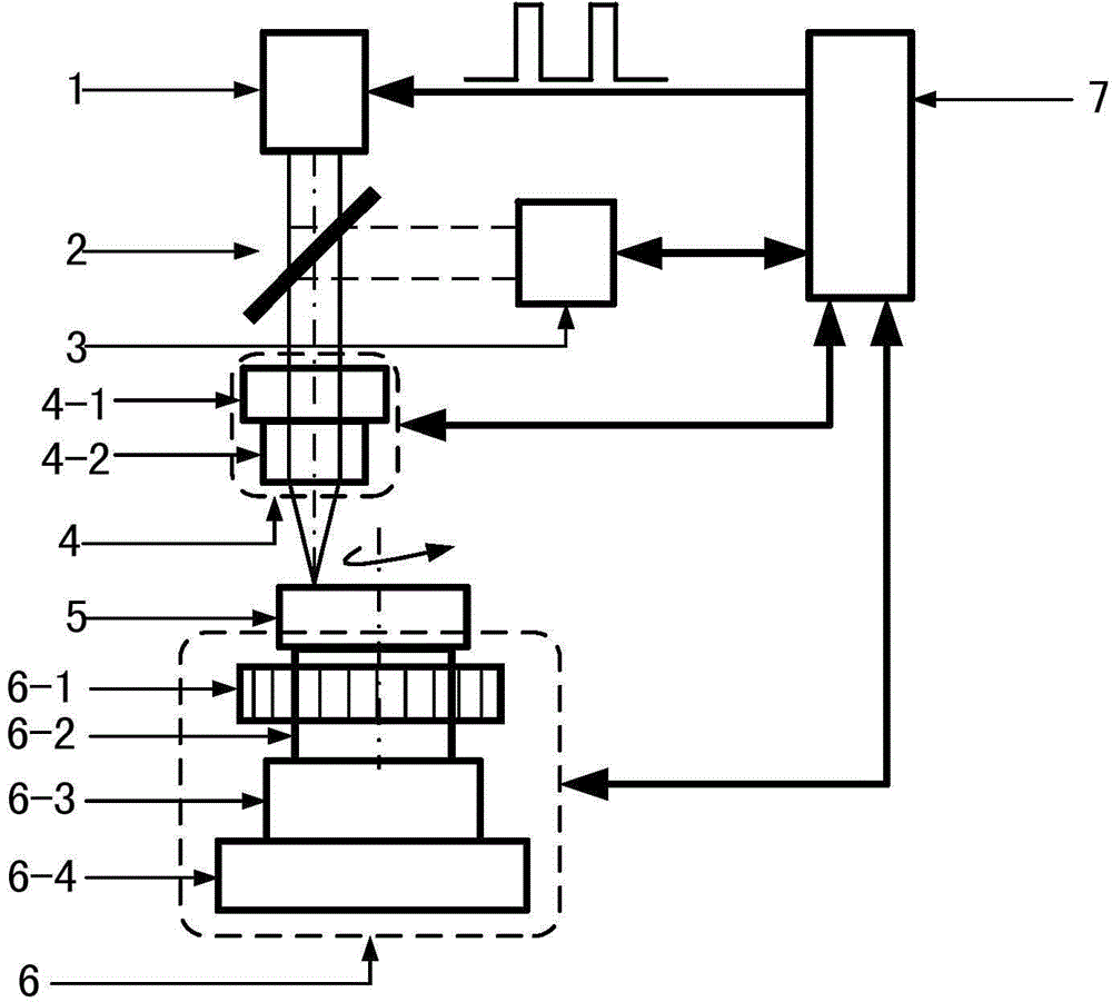
[0023] 1) Build a polar coordinate laser direct writing system:

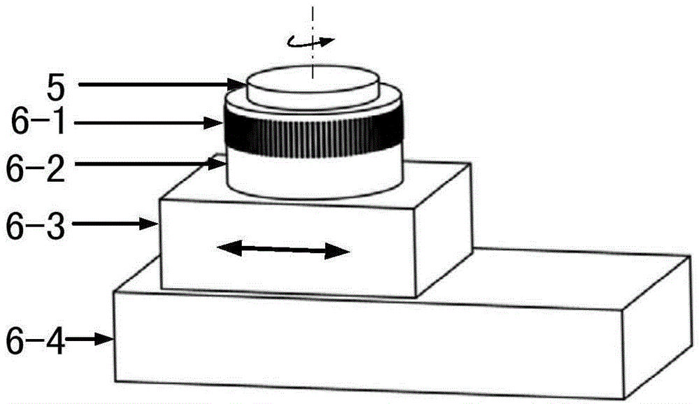
[0024] The system includes a modulatable laser light source module 1, a spectroscopic beam splitter 2, a defocus detection module 3, an adjustable focus converging objective lens module 4, a sample to be written 5, a rotary translation stage 6 and a general controller 7. The modulatable laser The light source module 1 and the out-of-focus detection module 3 are respectively located on both sides of the spectral beam splitter 2, and the angle between the optical axis of the light beam emitted by the modulated laser light source module 1 and the out-of-focus detection module 3 and the ...


PUM


Abstract

The invention relates to a method for a high-speed rotation laser direct-writing arbitrary graph. The method is mainly used for rapidly producing various micro-nano graph devices in central symmetry and non-central symmetry and with arbitrary distribution. The method comprises the steps of firstly establishing a set of polar coordinate laser direct-writing systems, then decomposing a to-be-inscribed arbitrary graph into a group of image data according to a spiral track in an equally-spacing manner, and finally dynamically adjusting a time interval between the transmission of the data of two adjacent inscribing points by virtue of a feedback control algorithm in the real inscribing process, so that the difference between a theoretical design position of one to-be-inscribed point and a real position is close to 0. The method has characteristics of simplicity in realization, high distribution precision of inscribing point positions, diversity in inscribing graph types and high practicability and has a wide application prospect in the field of the manufacture of the micro-nano graph device.

Description

technical field [0001] The invention relates to laser direct writing, in particular to a method for directly writing arbitrary graphics with a high-speed rotating laser, which is mainly applicable to the field of micro-nano processing. Background technique [0002] Laser direct writing is an advanced micro-nano processing technology, which has many advantages such as no mask, low cost, short processing cycle, flexible use, and low environmental requirements. The production and processing of devices has been widely used, and it is a practical technology with broad development prospects. According to different structures, the laser direct writing system can be divided into Cartesian coordinate system and polar coordinate system. Cartesian coordinate system direct writing system is suitable for processing rectangular orthogonal devices (such as semiconductor chips), but it has a great disadvantage in processing micro-nano devices with circular pattern distribution. It can only...

Claims


Application Information

Patent Timeline
Patent Type & Authority Applications(China)
IPC IPC(8): G03F7/20G03F7/207
Inventor 范永涛魏劲松王睿
Owner 杭州光学精密机械研究所
Why Eureka
Try Eureka