Method for building liquid seal of ORVR (onboard refueling vapor recovery) oil filling pipe

A technology of liquid sealing and refueling tubes, which is applied in special data processing applications, instruments, electrical digital data processing, etc., can solve the problems of inability to obtain test results, large manpower and material resources, and increased test costs, so as to facilitate popularization and application and reduce test costs. Cost, the effect of improving the sealing ability

Active Publication Date: 2015-05-06
YAPP AUTOMOTIVE PARTS
View PDF3 Cites 0 Cited by
  • Summary
  • Abstract
  • Description
  • Claims
  • Application Information

AI Technical Summary

Problems solved by technology

This method cannot obtain test results at the early stage of design, that is, before prototype production. Only after repeated cycles from sample manufacturing to test to design change can the final fuel oil pipe with liquid sealing performance be obtained.
Using the above method not only requires a lot of manpower and material resources, but also takes a long time and greatly increases the test cost.

Method used


Image

  • Method for building liquid seal of ORVR (onboard refueling vapor recovery) oil filling pipe
  • Method for building liquid seal of ORVR (onboard refueling vapor recovery) oil filling pipe
  • Method for building liquid seal of ORVR (onboard refueling vapor recovery) oil filling pipe

Examples


Embodiment 1

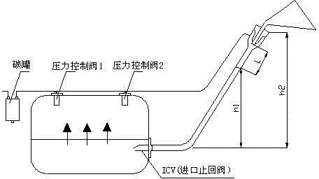
[0039] see figure 1 , a kind of method that establishes ORVR refueling pipe liquid seal, described method comprises the following steps:

[0040] 1) Measure the vertical distance from the fuel inlet of the fuel tank to the head of the filling pipe, h2=515mm;

[0041] 2) Select ICV, the inlet check valve, and measure its pressure drop. The pressure drop when the fuel flow Q is 38L / min is △P1=300Pa;

[0042] 3) Select the pressure control valve and measure its pressure drop. The pressure drop when the fuel vapor flow rate is 50L / min is △P2=90Pa;

[0043] 4) Select the carbon canister and measure its pressure drop. The pressure drop when the fuel vapor flow rate is 50 L / min is △P3=890Pa;

[0044] 5) The pressure generated by the liquid seal section in the oil filling pipe is P4, P4= ;

[0045] 6) The pressure generated by the fuel beam during refueling is P5, P5= ;

[0046] 7) The resistance generated between the fuel beam and the inner wall of the fuel pipe when refuelin...

Embodiment 2

[0068] see figure 1 , a kind of method that establishes ORVR refueling pipe liquid seal, described method comprises the following steps:

[0069] 1) Measure the vertical distance from the fuel inlet of the fuel tank to the head of the filling pipe, h2=515mm;

[0070] 2) Select ICV, the inlet check valve, and measure its pressure drop. The pressure drop when the fuel flow Q is 45L / min is △P1=340Pa;

[0071] 3) Select the pressure control valve and measure its pressure drop. The pressure drop when the fuel vapor flow rate is 55L / min is △P2=120Pa;

[0072] 4) Select the carbon canister and measure its pressure drop. The pressure drop when the fuel vapor flow rate is 55 L / min is △P3=940Pa;

[0073] 5) The pressure generated by the liquid seal section in the oil filling pipe is P4, P4= ;

[0074] 6) The pressure generated by the fuel beam during refueling is P5, P5= ;

[0075] 7) When refueling, the resistance generated between the fuel beam and the inner wall of the refuel...

Embodiment 3

[0097] see figure 1 , a kind of method that establishes ORVR refueling pipe liquid seal, described method comprises the following steps:

[0098] 1) Measure the vertical distance from the fuel inlet of the fuel tank to the head of the filling pipe, h2=515mm;

[0099] 2) Select ICV, the inlet check valve, and measure its pressure drop. The pressure drop when the fuel flow Q is 15L / min is △P1=140Pa;

[0100] 3) Select the pressure control valve and measure its pressure drop. The pressure drop when the fuel vapor flow rate is 19L / min is △P2=70Pa;

[0101] 4) Select the carbon canister and measure its pressure drop. The pressure drop when the fuel vapor flow rate is 19 L / min is △P3=370Pa;

[0102] 5) The pressure generated by the liquid seal section in the oil filling pipe is P4, P4= ;

[0103] 6) The pressure generated by the fuel beam during refueling is P5, P5= ;

[0104] 7) When refueling, the resistance generated between the fuel beam and the inner wall of the refueli...


PUM


Abstract

The invention discloses a method for building a liquid seal of an ORVR (onboard refueling vapor recovery) oil filling pipe. By computing relevance structure parameters, the inner diameter of the oil filling pipe is obtained, and thus, the liquid seal can be formed in the oil filling pipe, and the phenomenon that the liquid seal cannot be formed due to the fact that the inner diameter of the oil filling pipe is overlarge is avoided; if the inner diameter of the oil filling pipe is undersize, the negative effects, such as reverse spraying of fuel oil, in an oil filling process can be produced. According to the method, the sealing ability of liquid is greatly increased, and the development efficiency of a product is increased; moreover, a large number of manpower and material resources are saved, the development cycle is shortened, the experimentation cost is reduced, and the method can be conveniently popularized and applied on a large scale.

Description

technical field [0001] The invention relates to a method for establishing a liquid seal of an ORVR fueling pipe, and belongs to the technical field of liquid sealing of a fueling pipe. Background technique [0002] With the continuous increase of domestic automobile production, automobile emissions have become an important source of urban air pollution, and the oil and gas emissions from vehicle gasoline are the main pollution source of automobile emissions. Therefore, in order to improve the quality of the atmospheric environment, countries have formulated more and more The more stringent automobile emission regulations, the stricter automobile fuel evaporative emission regulations are also formulated. Therefore, the control of gasoline vehicle fuel evaporation pollutants is an important direction for the control of vehicle emission pollutants. Gasoline vehicle fuel evaporation pollutants mainly include running loss, pervaporative emissions, and refueling emissions, and re...

Claims


Application Information

Patent Timeline
Patent Type & Authority Applications(China)
IPC IPC(8): G06F19/00
Inventor 孙岩姜林刘亮朱志勇朱明泽苏卫东薛晴
Owner YAPP AUTOMOTIVE PARTS
Why Eureka
Try Eureka