A method of establishing an orvr filling pipe liquid tight
A liquid sealing and filling pipe technology, which is applied in special data processing applications, instruments, electrical and digital data processing, etc. ability, the effect of reducing the cost of testing
- Summary
- Abstract
- Description
- Claims
- Application Information
AI Technical Summary
Problems solved by technology
Method used
Image
Examples
Embodiment 1
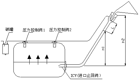
[0039] see figure 1 , a kind of method that establishes ORVR refueling pipe liquid seal, described method comprises the following steps:
[0040] 1) Measure the vertical distance from the fuel inlet of the fuel tank to the head of the filling pipe, h2=515mm;
[0041] 2) Select ICV, the inlet check valve, and measure its pressure drop. The pressure drop when the fuel flow Q is 38L / min is △P1=300Pa;
[0042] 3) Select the pressure control valve and measure its pressure drop. The pressure drop when the fuel vapor flow rate is 50L / min is △P2=90Pa;
[0043] 4) Select the carbon canister and measure its pressure drop. The pressure drop when the fuel vapor flow rate is 50 L / min is △P3=890Pa;
[0044] 5) The pressure generated by the liquid seal section in the oil filling pipe is P4, P4= ;
[0045] 6) The pressure generated by the fuel beam during refueling is P5, P5= ;
[0046] 7) When refueling, the resistance generated between the fuel beam and the inner wall of the refueli...
Embodiment 2
[0068] see figure 1 , a kind of method that establishes ORVR refueling pipe liquid seal, described method comprises the following steps:
[0069] 1) Measure the vertical distance from the fuel inlet of the fuel tank to the head of the filling pipe, h2=515mm;
[0070] 2) Select ICV, the inlet check valve, and measure its pressure drop. The pressure drop when the fuel flow Q is 45L / min is △P1=340Pa;
[0071] 3) Select the pressure control valve and measure its pressure drop. The pressure drop when the fuel vapor flow rate is 55L / min is △P2=120Pa;
[0072] 4) Select the carbon canister and measure its pressure drop. The pressure drop when the fuel vapor flow rate is 55 L / min is △P3=940Pa;
[0073] 5) The pressure generated by the liquid seal section in the oil filling pipe is P4, P4= ;
[0074] 6) The pressure generated by the fuel beam during refueling is P5, P5= ;
[0075] 7) When refueling, the resistance generated between the fuel beam and the inner wall of the refuel...
Embodiment 3
[0097] see figure 1 , a kind of method that establishes ORVR refueling pipe liquid seal, described method comprises the following steps:
[0098] 1) Measure the vertical distance from the fuel inlet of the fuel tank to the head of the filling pipe, h2=515mm;
[0099] 2) Select ICV, the inlet check valve, and measure its pressure drop. The pressure drop when the fuel flow Q is 15L / min is △P1=140Pa;
[0100] 3) Select the pressure control valve and measure its pressure drop. The pressure drop when the fuel vapor flow rate is 19L / min is △P2=70Pa;
[0101] 4) Select the carbon canister and measure its pressure drop. The pressure drop when the fuel vapor flow rate is 19 L / min is △P3=370Pa;
[0102] 5) The pressure generated by the liquid seal section in the oil filling pipe is P4, P4= ;
[0103] 6) The pressure generated by the fuel beam during refueling is P5, P5= ;
[0104] 7) When refueling, the resistance generated between the fuel beam and the inner wall of the refueli...
PUM
 Abstract
Description
Claims
Application Information
 - R&D
- Intellectual Property
- Life Sciences
- Materials
- Tech Scout
- Unparalleled Data Quality
- Higher Quality Content
- 60% Fewer Hallucinations
Browse by: Latest US Patents, China's latest patents, Technical Efficacy Thesaurus, Application Domain, Technology Topic, Popular Technical Reports.
© 2025 PatSnap. All rights reserved.Legal|Privacy policy|Modern Slavery Act Transparency Statement|Sitemap|About US| Contact US: help@patsnap.com


