
Numerical control machining center tool changing and machining process demonstration teaching aid

A machining process and machining center technology, which is applied in the field of CNC machining center tool change and machining process demonstration teaching aids, can solve the problems that teaching is not intuitive and difficult for students to understand, and achieves the effect of facilitating upgrade and replacement and solving hysteresis problems.

Inactive Publication Date: 2015-05-06
SOUTHWEST PETROLEUM UNIV
View PDF5 Cites 1 Cited by
  • Summary
  • Abstract
  • Description
  • Claims
  • Application Information

AI Technical Summary

Problems solved by technology

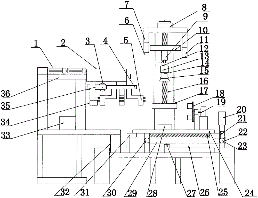
[0003] The purpose of the present invention is to provide a demonstration of tool change and machining process of CNC machining center in order to assist teachers to demonstrate the relevant knowledge of CNC technology and CNC equipment in theoretical classrooms, and solve the problem that traditional classroom teaching is not intuitive enough and students are difficult to understand teaching aids

Method used


Image

  • Numerical control machining center tool changing and machining process demonstration teaching aid
  • Numerical control machining center tool changing and machining process demonstration teaching aid
  • Numerical control machining center tool changing and machining process demonstration teaching aid

Examples


Embodiment Construction

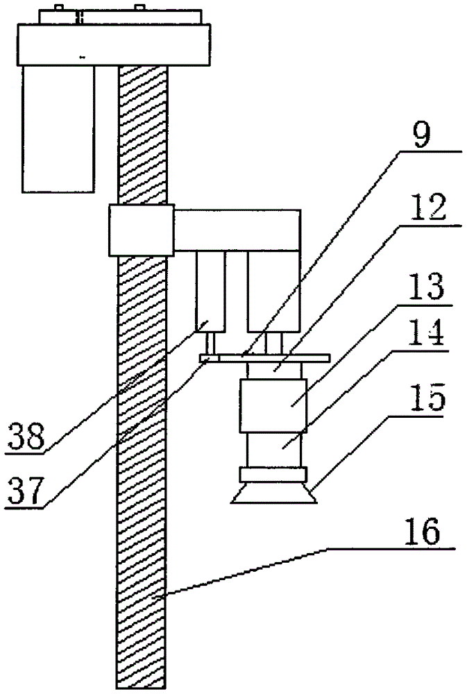
[0016] 1. Return to the origin: Press the switch a on the console 26, the motor A8 drives the worm B16 to rotate, the main shaft moves upwards driven by the worm slider 10, and stops after touching the travel switch B7. The workbench 24, under the action of the worm slider driven by the motor C20 and the motor D22, is limited by the travel switch D21 and the travel switch E31, and reaches the origin position specified by the x and y axes, and the indicator light 27 on the console 26 lights up to realize Demonstration of the process of returning to the origin;

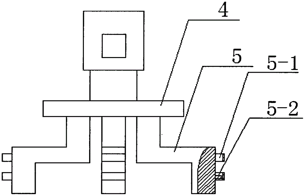
[0017] 2. Tool clamping: press the switch b on the console 26, the air pump 33 starts, the tool magazine reaches the bottom of the main shaft driven by the cylinder 1, the worm A3 rotates under the drive of the motor E35, and drives the disc-shaped gear 4 to rotate, and the The tool to be clamped moves directly below the main shaft, the motor A8 drives the worm B16 to rotate, the main shaft moves downwards driven by the...


PUM


Abstract

The invention relates to a numerical control machining center tool changing and machining process demonstration teaching aid for relevant professional teaching of mechanical engineering of engineering colleges, and solves the problem that traditional classroom teaching is not visual and vivid enough and is difficultly understood by students. The technical scheme includes that in a tool magazine portion, a tool apron is lapped below a disc-shaped gear, the left side of the gear is engaged with a worm A, the worm A is connected with a motor E, a switch F is mounted below the motor E integrally mounted on a hollow square sleeve, the sleeve sleeves a guide rail, the left side of the sleeve is connected with a cylinder, the cylinder is mounted on the guide rail and connected with an air pump, in a spindle portion, a worm B is connected with a motor A, a worm slider is mounted on two supporting rods, a worktable is mounted on a worm slider mechanism, a chuck, a motor B and a vise are mounted on the worktable, and a support column, a switch, a worm E, a console and a worm C are lapped on a bottom plate. The demonstration teaching aid demonstrates all working processes of machining centers, and helps the students to understand tool changing, tool setting and tool tracks.

Description

Technical field: [0001] The invention relates to a teaching aid for tool change and machining process demonstration of a numerical control machining center used for the teaching of mechanical engineering in engineering colleges. Background technique: [0002] In classroom teaching, students are exposed to numerical control technology for the first time and do not have a deep understanding of the real objects. Pictures, videos and other forms in traditional classrooms are difficult to meet the needs of students to deeply understand the structure of CNC equipment and its complex motion process. Large-scale CNC equipment cannot enter the theoretical classroom of CNC technology and equipment knowledge explanation. There is noise in the equipment at the CNC machining site, which affects the teaching quality of teachers explaining the theoretical knowledge of CNC technology at the processing site. Due to potential safety hazards, some action details are difficult for students to o...

Claims


Application Information

Patent Timeline
Patent Type & Authority Applications(China)
IPC IPC(8): G09B25/02
CPCG09B25/02
Inventor 黄建明苗杰司虚符伟督涂庆谢友春
Owner SOUTHWEST PETROLEUM UNIV
Learn More