Electric auxiliary pressurization system and application method thereof

A supercharging system and electric auxiliary technology, applied in the direction of charging system, engine components, combustion engine, etc., can solve the problems of weak supercharging effect and difficult installation, achieve strong supercharging effect, small installation difficulty, solve magnetic effect of stagnation

Inactive Publication Date: 2016-06-01
DONGFENG COMML VEHICLE CO LTD
View PDF8 Cites 8 Cited by
  • Summary
  • Abstract
  • Description
  • Claims
  • Application Information

AI Technical Summary

Problems solved by technology

[0006] The purpose of the present invention is to overcome the defects and problems in the prior art that the supercharging effect is weak and the installation is difficult, and to provide an electric auxiliary supercharging system with a strong supercharging effect and a small installation difficulty and its use method

Method used


Image

  • Electric auxiliary pressurization system and application method thereof
  • Electric auxiliary pressurization system and application method thereof

Examples


Embodiment 1

[0050] see figure 1 and figure 2 :

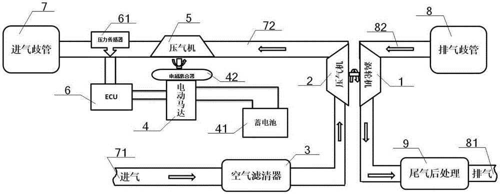
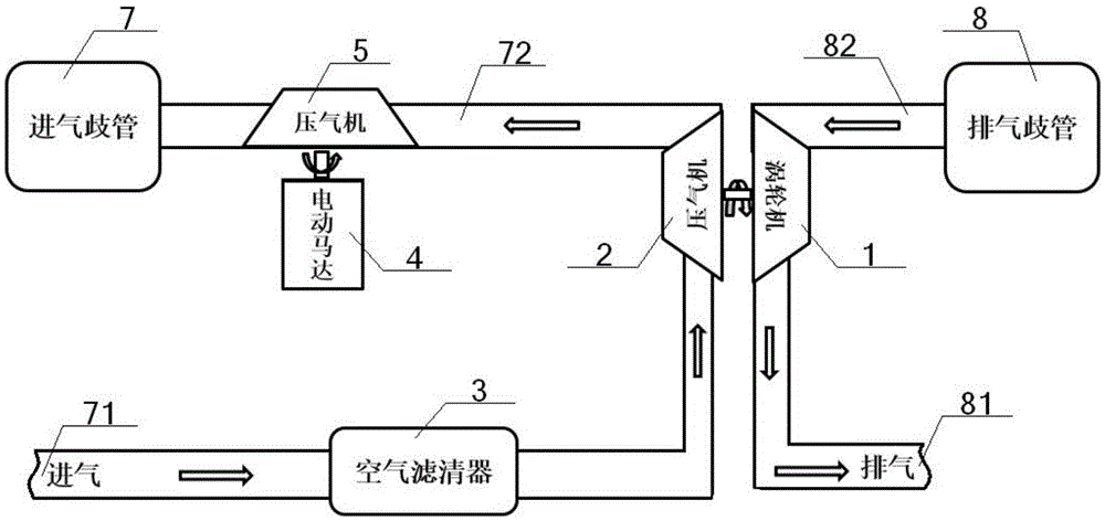
[0051] Structurally: an electric auxiliary supercharging system, including an exhaust gas turbine 1, an exhaust gas compressor 2, an air filter 3, an electric motor 4 and an auxiliary compressor 5, the output end of the electric motor 4 is connected to the auxiliary compressor 5 The driving shaft of the impeller is connected, and one end of the air filter 3 communicates with the air inlet 71, and the other end successively passes through the impeller air channel in the exhaust compressor 2 and the impeller air channel in the auxiliary compressor 5, and then connects with the air intake port. The gas manifold 7 communicates, the impeller in the exhaust gas compressor 2 is coaxially connected with the turbine in the exhaust gas turbine 1, the inlet port of the turbine air passage in the exhaust gas turbine 1 communicates with the exhaust manifold 8, and the gas outlet communicates with the exhaust gas exhaust port 81 are connected.

[005...

Embodiment 2

[0054] Basic content is the same as embodiment 1, the difference is:

[0055] Structurally: a pressure sensor 61 is arranged on the position between the intake manifold 7 and the auxiliary compressor 5 in the intake passage 72, the output end of the pressure sensor 61 is connected to the input end signal of the ECU6, and the output end of the ECU6 Terminal is connected with the input signal of electric motor 4.

[0056] On the method: the pressure value in the air inlet 72 is measured by the pressure sensor 61, and the measured value is transmitted to the ECU6 immediately; the operation of the electric motor 4 driving the auxiliary compressor 5 means that the ECU6 controls the electric motor 4 to Driving the auxiliary compressor 5 to run; the electric motor 4 and the auxiliary compressor 5 to stop running means that the ECU 6 controls the electric motor 4 to stop running so that the auxiliary compressor 5 stops running.

Embodiment 3

[0058] Basic content is the same as embodiment 2, the difference is:

[0059] Structurally: the output end of the electric motor 4 is connected with the drive shaft of the impeller in the auxiliary compressor 5 through the electromagnetic clutch 42 . The electromagnetic clutch 42 is preferably a multi-disc electromagnetic clutch.

[0060] In terms of method: the ECU6 controls the electric motor 4 to drive the auxiliary compressor 5 to run, which means: the ECU6 controls the electromagnetic clutch 42 to close to conduct the electric motor 4 and the auxiliary compressor 5, thereby driving the auxiliary compressor 5 to run; the ECU6 controls The stopping of the electric motor 4 means that the ECU 6 controls the electromagnetic clutch 42 to disconnect, and the electric motor 4 and the auxiliary compressor 5 stop running.


PUM


Abstract

An electric auxiliary pressurization system comprises a waste gas turbine motor, a waste gas compressor, an air filter, an electric motor and an auxiliary gas compressor. The output end of the electric motor is connected with a drive shaft of an impeller in the auxiliary gas compressor. One end of the air filter communicates with an air inlet, and the other end of the air filter sequentially passes through the waste gas compressor and an impeller gas flue in the auxiliary gas compressor to communicate with an intake manifold. An impeller in the waste gas compressor is coaxially connected with a turbine in the waste gas turbine motor. The two ends of the waste gas turbine motor communicate with an exhaust manifold and a waste gas outlet. During using, the electric motor drives the auxiliary gas compressor firstly to provide compressed air for an engine, the waste gas turbine motor and the waste gas compressor can work accordingly, and when the output of the engine is larger and larger, electric pressurization gradually retreats till waste gas turbine pressurization completely replaces electric pressurization. According to the electric auxiliary pressurization system, the problem of hysteresis of an exhaust gas turbocharger can be solved, the pressurization effect is good, precision is relatively high, and the installing difficulty is relatively low.

Description

technical field [0001] The invention relates to an electric auxiliary supercharging technology, in particular to an electric auxiliary supercharging system and its use method, which is specifically applicable to improving the supercharging effect and reducing the difficulty of installation on the basis of solving the hysteresis problem of the exhaust gas turbocharger . Background technique [0002] The traditional turbocharger uses the inertial momentum of the exhaust gas from the engine to drive the turbine in the turbine chamber, and the turbine drives the coaxial compressor impeller. The compressor impeller presses the air sent by the air filter pipe to make it boost into the cylinder. When the engine speed increases (such as when accelerating), the discharge speed of the exhaust gas and the speed of the turbine also increase synchronously, and the impeller of the compressor can compress more air into the cylinder, and the pressure and density of the air increase accordi...

Claims


Application Information

Patent Timeline
Patent Type & Authority Applications(China)
IPC IPC(8): F02B37/04F02B39/10F02M35/10F02B37/14
CPCF02B37/04F02B37/14F02B39/10F02M35/10157Y02T10/12
Inventor 许振营姜江程伟胡前
Owner DONGFENG COMML VEHICLE CO LTD
Why Eureka
Try Eureka