
High-efficiency switched capacitor power converter

A technology of power converters and switched capacitors, which is applied in the direction of conversion equipment without intermediate conversion to AC, photovoltaic power generation, electrical components, etc., and can solve the problems of weakening the working efficiency of the circuit and increasing the difficulty of output voltage control

Inactive Publication Date: 2017-12-15
SUN YAT SEN UNIV
View PDF2 Cites 11 Cited by
  • Summary
  • Abstract
  • Description
  • Claims
  • Application Information

AI Technical Summary

Problems solved by technology

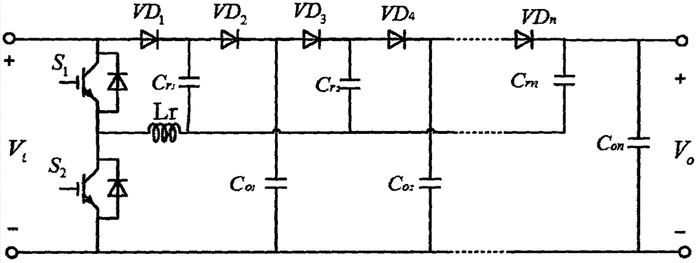
[0005] However, in the attached figure 1 In the shown step-up resonant switched capacitor converter, the relationship between its input and output voltage is only determined by the topology of the circuit (that is, the order n), which increases the difficulty of controlling the output voltage
At the same time, because there is a certain conduction voltage drop on the diode, it will weaken the working efficiency of the circuit

Method used


Image

  • High-efficiency switched capacitor power converter
  • High-efficiency switched capacitor power converter
  • High-efficiency switched capacitor power converter

Examples


Embodiment 1

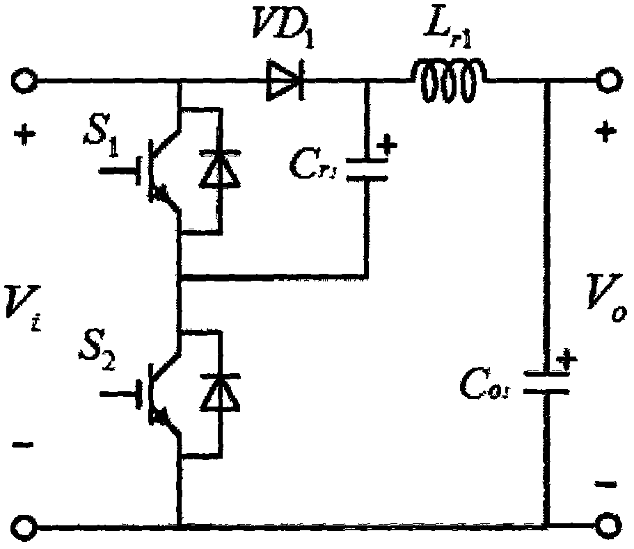
[0027] attached by figure 2 It can be seen that a high-efficiency switched capacitor power converter of the present invention is characterized in that the switched capacitor power converter includes a power switch S 1 , power switch S 2 , diode VD 1 , capacitance C r1 , inductance L r1 , capacitance C o1 . power switch S 1 collector and diode VD 1 The positive pole of the power supply is connected to the positive input terminal of the power supply, and the power switch S 1 The emitter and power switch S 2 The collector is connected to the capacitor C r1 Negative pole; power switch S 2 The emitter stage and capacitor C o1 The negative poles of the diodes are connected to the negative input terminal of the input power supply; the diode VD 1 The negative pole and the capacitor C r1 The anode of the common connection to the inductor L r1 One end of the inductance L r1 the other end of the capacitor C o1 The positive pole of the output power supply is connected to ...

Embodiment 2

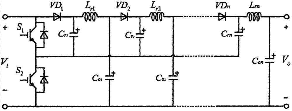
[0031] In the photovoltaic power generation system, a third-order circuit of a high-efficiency switched capacitor power converter of the present invention is used as a DC boost module, and the attached Figure 5 It can be seen that a 3-stage circuit of a high-efficiency switched capacitor power converter of the present invention includes a solar panel input power supply V i , power switch S 1 , power switch S 2 , diode VD 1 , VD 2 , VD 3 , capacitance C r1 、C r2 、C r3 , capacitance C o1 、C o2 、C o3 and inductance L r1 , L r2 , L r3 . power switch S 1 collector and diode VD 1 The anode of the common connected to the power supply V i Positive input terminal, power switch S 1 The emitter and power switch S 2 The collector is connected to the capacitor C r1 Negative pole, power switch S 2 The emitter stage and capacitor C o1 The negative poles of the diodes are connected to the negative input terminal of the input power supply; the diode VD 1 The negative pol...


PUM


Abstract

The invention discloses a high-efficiency switched capacitor power converter which is characterized in that the switched capacitor power converter comprises a power switch S1, a power switch S2, a diode VD1, a capacitor Cr1, an inductor Lr1 and a capacitor Co1. Compared with a traditional boost resonant switched capacitor converter, according to the switched capacitor power converter of the invention, a small inductor is used to substitute a diode to realize freewheeling in a circuit, the conduction loss of the switched capacitor converter is reduced, at the same time, the voltage regulation of a PWM control mode is realized through the resonance of the inductor and a switched capacitor, and a hysteresis problem of the traditional switched capacitor converter under a voltage following mode is solved. A single switch of a topology can work under PWM control to realize zero current conduction, and the switching loss of the converter is reduced. Therefore, compared with the traditional boost resonant switched capacitor converter, the switched capacitor power converter has the advantages that the control of output voltage is realized, and the working efficiency is improved.

Description

technical field [0001] The invention belongs to the field of power conversion equipment, and in particular relates to a high-efficiency switched capacitor power converter. technical background [0002] Nowadays, in the design of power converters, how to balance efficiency and cost has always been the focus of attention. On the one hand, it is the development of new materials and new devices, such as the development of new technology for devices and the invention of new semiconductor materials; on the other hand, It is the invention of new topology technology and control method. The switched capacitor power converter has the advantages of small size, light weight, low magnetization, etc., and has great application prospects in power conversion systems. So the research of high-efficiency switched capacitor power converter is an important research direction. [0003] attached figure 1 It is a multi-level topology diagram of a traditional step-up resonant switched capacitor c...

Claims


Application Information

Patent Timeline
IPC IPC(8): H02M3/07H02J3/38
CPCH02J3/383H02M3/07H02M1/007Y02E10/56
Inventor 付青耿炫赖日培
Owner SUN YAT SEN UNIV
Learn More