
Sliding contacts for high voltage appliances

A technology of sliding contacts and high-voltage electrical appliances, which is applied in the direction of contact engagement, etc., can solve the problems of easy deformation of contacts, no isolation, low carrying capacity, etc., and achieve reliable and stable motion structure, good dynamic and thermal stability, and improved stability sexual effect

Active Publication Date: 2017-05-17
GUANGDONG JINHUILONG SWITCH
View PDF5 Cites 0 Cited by
  • Summary
  • Abstract
  • Description
  • Claims
  • Application Information

AI Technical Summary

Problems solved by technology

[0003] Among them, the sliding contact finger is a spring contact finger made of copper sheet or copper wire spring. Since the spring contact finger is relatively thin, the contact method is point contact, and it is fixed in the contact finger placement block, so that the sliding contact exists The following disadvantages: the utilization rate of the contact surface between the spring contact finger and the moving main contact is low, the resistance is large, the carrying capacity is low, the shape of the contact finger is easy to change, and it cannot be guaranteed that all the sliding contacts can be fully attached to the moving main contact at all times , Poor dynamic and thermal stability, generally only used as a current transmission part, does not have the function of isolation, and the stability of current transmission is average

Method used


Image

  • Sliding contacts for high voltage appliances
  • Sliding contacts for high voltage appliances
  • Sliding contacts for high voltage appliances

Examples


Embodiment Construction

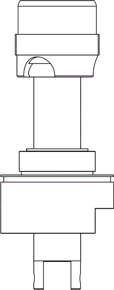
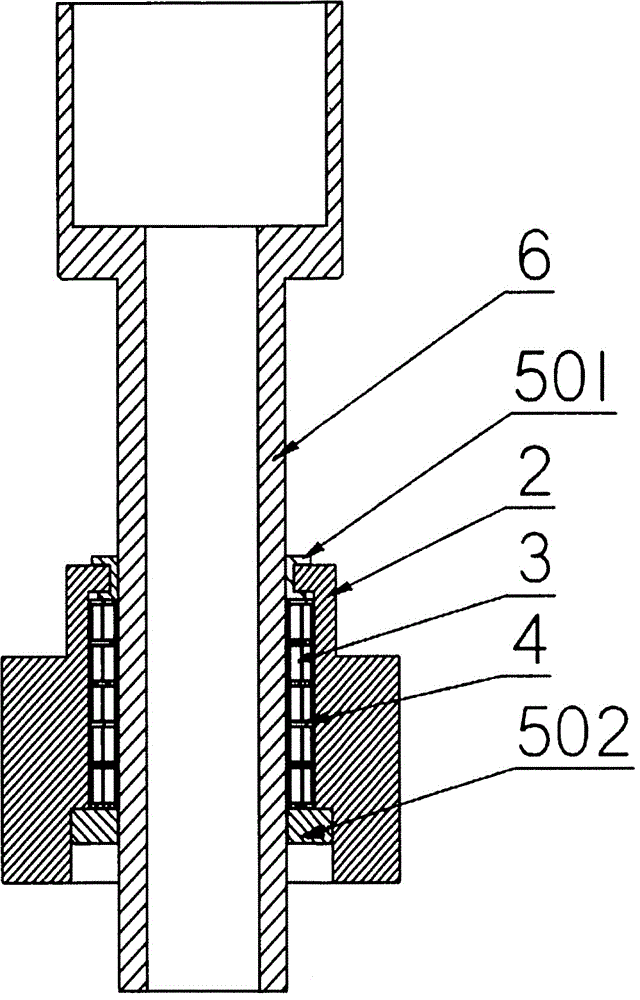
[0021] Such as Figure 1-7 As shown, the sliding contact used for high-voltage electrical appliances in this preferred embodiment includes contact finger placement block 2, sliding contact finger 3, contact finger separator 4, upper lubricating guide sleeve 501, lower lubricating guide sleeve 502, active drive The contact 6, wherein the contact finger placement block 2, the moving main contact 6 and the sliding contact finger 3 are in contact with each other.

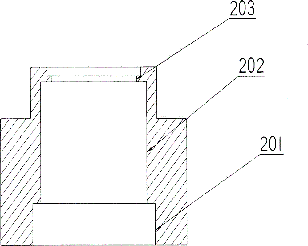
[0022] The sliding contact is composed of a contact finger placement block 2, 5 sliding contact fingers 3, 6 contact finger partitions 4, an upper lubricating guide sleeve 501 and a lower lubricating guide sleeve 502, and all the sliding contact fingers 3 are rolled into a ring Insert into the hole 202 in the contact finger placement block, pad the contact finger separator 4 between two sliding contact fingers 3, and finally form a hollow sleeve, the outer diameter of the sliding contact finger 3 is in contact with the ...


PUM


Abstract

A sliding contact used for high-voltage electric appliances comprises a contact finger containing block, slide contact fingers, contact finger partition plates, lubrication guide sleeves and a movable main contact. At least two slide contact fingers are embedded in the sliding contact. Every two adjacent slide contact fingers are separated through the corresponding contact finger partition plate, a hollow sleeve for the movable main contact to penetrate through is formed, the lubrication guide sleeves are arranged at the upper port and the lower port of the sleeve respectively, the movable main contact penetrates through the sliding contact, and the circumferential face of the movable main contact makes contact with the slide contact fingers. The slide contact fingers are small in contact resistance and large in passable carrying capacity; current is transmitted between the sliding contact and the movable main contact only through the slide contact fingers, and therefore the stability of current transmission is greatly improved; limiting is conducted through the elastic attaching of the contact fingers by means of the lubrication guide sleeves, the whole movement structure is reliable and stable, the bad contact caused when the contact fingers deform due to the movement process can not happen, the sliding contact and the movable main contact are kept making contact with the slide contact fingers all the time, and the dynamic thermal stability is high.

Description

technical field [0001] The invention relates to a conductive sliding connection part of a high-voltage electrical appliance, in particular to a sliding contact for a high-voltage electrical appliance. Background technique [0002] Sliding contact is a kind of conductive sliding connection part used in high voltage electrical appliances. Existing sliding contacts are generally composed of sliding contact fingers, contact finger placement blocks, and moving main contacts. [0003] Among them, the sliding contact finger is a spring contact finger made of copper sheet or copper wire spring. Since the spring contact finger is relatively thin, the contact method is point contact, and it is fixed in the contact finger placement block, so that the sliding contact exists The following disadvantages: the utilization rate of the contact surface between the spring contact finger and the moving main contact is low, the resistance is large, the carrying capacity is low, the shape of the ...

Claims


Application Information

Patent Timeline
Patent Type & Authority Patents(China)
IPC IPC(8): H01H1/36
CPCH01H1/36
Inventor 吴鸿彬陈升庭纪锐宏郑康铭纪顺峰
Owner GUANGDONG JINHUILONG SWITCH
Learn More