Laminar plasma jet stabilizing method

A plasma and stable laminar flow technology, applied in the field of plasma jet, can solve the problems of increasing the difficulty of plasma source control, unreasonable use of energy resources, and increasing the volume of plasma source, so as to reduce the pressure difference and improve effect, the effect of increasing the contact area

Inactive Publication Date: 2015-05-06
CHENGDU PLASMAJET SCI & TECH
View PDF8 Cites 3 Cited by
  • Summary
  • Abstract
  • Description
  • Claims
  • Application Information

AI Technical Summary

Problems solved by technology

[0005] In order to solve the reaction force of the working gas in the arc channel to the gas in the air flow channel, the above-mentioned prior art heats the working gas entering the air flow channel, but this method increases the volume of the plasma source to a certain extent, increases the The control difficulty of the plasma source is increased, and the energy resources are not used reasonably, resulting in a certain waste of resources

Method used


Image

  • Laminar plasma jet stabilizing method
  • Laminar plasma jet stabilizing method
  • Laminar plasma jet stabilizing method

Examples


Embodiment 1

[0028] As a preferred embodiment of the present invention, this embodiment discloses a method for stabilizing a laminar plasma jet, and this embodiment includes the following steps:

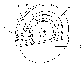
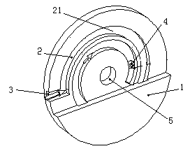
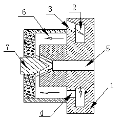
[0029] Cooling step: when the plasma source is working, the working gas first enters the inside of the anode body, and when the working gas circulates inside the anode body, the working gas cools the anode body, and at the same time, the excess energy on the anode body is transmitted to the working gas, and the working gas The temperature is raised; the working gas is then output from the anode body to the

[0030] Airflow transportation steps: the working gas circulates in the airflow channel between the casing and the anode body, and the temperature of the working gas in the airflow channel is maintained or continuously raised; then transported to

[0031] Plasma jet step: the working gas flows from the gas flow channel into the arc channel, the working gas is heated and ionized into plasma in ...

Embodiment 2

[0033] As another preferred embodiment of the present invention, this embodiment discloses a method for stabilizing a laminar plasma jet, and this embodiment includes the following steps:

[0034] Cooling step: when the plasma source is working, the working gas first enters the inside of the anode body, and when the working gas circulates inside the anode body, the working gas cools the anode body, and at the same time, the excess energy on the anode body is transmitted to the working gas, and the working gas The temperature is raised; the working gas is then output from the anode body to the

[0035] Airflow transportation steps: the working gas circulates in the airflow channel between the casing and the anode body, and the temperature of the working gas in the airflow channel is maintained or continuously raised; then transported to

[0036] Plasma jet step: the working gas flows from the gas flow channel into the arc channel, the working gas is heated and ionized into plas...

Embodiment 3

[0040] As another preferred embodiment of the present invention, this embodiment discloses a method for stabilizing a laminar plasma jet, and this embodiment includes the following steps:

[0041] Cooling step: when the plasma source is working, the working gas first enters the inside of the anode body, and when the working gas circulates inside the anode body, the working gas cools the anode body, and at the same time, the excess energy on the anode body is transmitted to the working gas, and the working gas The temperature is raised; the working gas is then output from the anode body to the

[0042]Airflow transportation steps: the working gas circulates in the airflow channel between the casing and the anode body, and the temperature of the working gas in the airflow channel is maintained or continuously raised; then transported to

[0043] Plasma jet step: the working gas flows from the gas flow channel into the arc channel, the working gas is heated and ionized into plasm...


PUM


Abstract

The invention discloses a laminar plasma jet stabilizing method and relates to the technical field of plasma jets. The method includes when a plasma source operates, allowing the operation gas to enter an anode member to flow into a gas channel of the plasma source and enters an arc channel finally. The method is simple, the heat released in the anode member cooling process can be utilized reasonably to heat the operation gas, the pressure of the operation gases inside and outside the arc channel can be reduced, the plasma jet can be stabilized, the self cooling of the plasma source can be implemented, the anode member energy utilization rate can be increased, energy waste can be avoided, and the heating efficiency of a high laminar plasma generator can be improved.

Description

technical field [0001] The invention relates to the technical field of plasma jets, more precisely to a method for stabilizing laminar plasma jets. Background technique [0002] Inside the plasma generator, the gas temperature in the gas flow channel is very different from the gas temperature in the arc channel, and the gas pressure in the two channels is different in a certain space volume, and the gas in the arc channel produces a reverse thrust on the gas in the gas flow channel. The working gas flow rate of the laminar plasma jet is generally very small, only about 1-30slpm. This reverse thrust will cause a short-term blockage of the airflow in the airflow channel, and then the reverse thrust will be reduced until it disappears, and the blockage will be eliminated. When the laminar plasma generator is working, this reverse thrust will be generated and disappeared periodically, which causes the laminar plasma jet to be unstable. [0003] In addition, the gas flow channel...

Claims


Application Information

Patent Timeline
Patent Type & Authority Applications(China)
IPC IPC(8): H05H1/28
Inventor 王鹏飞黄佳华杨超赵华任琼英李向阳李露
Owner CHENGDU PLASMAJET SCI & TECH
Why Eureka
Try Eureka