Self-aligning micro spray nozzle with control grid

A control grid and self-alignment technology, applied in printing and other directions, can solve the problems of narrowing the application field of EHD printing technology, complex structure, and pitch changes

Inactive Publication Date: 2009-12-02
XIAMEN UNIV
View PDF0 Cites 2 Cited by
  • Summary
  • Abstract
  • Description
  • Claims
  • Application Information

AI Technical Summary

Problems solved by technology

The same size nozzle, the latter can obtain smaller droplets, and help to form a stable Taylor cone, reduce the initial injection voltage, but the structure is relatively complex ([2] Yuji ISHIDA et al., Japanese Journal of Applied Physics Vol.44, No.7B, 2005, pp.5786-5790; [3] Yuji ISHIDA et al., Japanese Journal of Applied Physics, Vol.45, 2006, 6475)
In the experimental devices used by most research groups, in order to obtain a strong enough electric field, electrodes are set on the nozzle and the substrate, and are connected to the two poles of the high-voltage power supply, which requires that the substrate between the nozzle and the substrate electrode must be Good conductive material, otherwise it will weaken the distribution of the space electric field and affect the printing effect. This defect limits the use of non-conductive substrates and reduces the application field of EHD printing technology; in addition, this structure also has another Defects: Due to the poor flatness of the substrate surface and other reasons, it is easy to cause changes in the distance between the substrate and the nozzle, which seriously affects the stability of droplet ejection ([3] Yuji ISHIDA et al., Japanese Journal of Applied Physics, Vol.45 , 2006, 6475), which has become a major obstacle to the practical and commercialization of electro-hydraulic coupled micro-jet printing technology
Their research group used the DRIE process and the anodic oxidation method to fabricate micro-nozzles with tip sizes of 20 μm and 5 μm respectively. Although droplets with a diameter of less than 20 μm can be sprayed, the spray stability is poor and the droplet size is not uniform.
The main reason is that due to the use of an external control grid structure, in order to realize that the droplet passes through the small hole in the center of the grid to reach the substrate under the action of the grid control voltage, it is necessary to ensure that the spatial electric field where the droplet is located is distributed symmetrically in the horizontal direction. That is to say, the force balance of the droplet in the direction parallel to the substrate requires strict alignment between the center of the nozzle and the small hole in the center of the grid, otherwise the droplet will be adsorbed to the surface of the grid after leaving the needle tip, and it will not be possible to deposit patterns on the substrate. Corrosion of the grid; In addition, the distance between the grid and the nozzle is one of the important parameters affecting the injection performance. Practical Jetting Performance of Structures
If the direct bonding technology of the micromachining process is used, it is limited to the current equipment level, the alignment accuracy before bonding is low, and the accuracy that can be achieved by directly bonding two planes cannot meet the alignment accuracy of the nozzle and the grid in this structure Require

Method used


Image

  • Self-aligning micro spray nozzle with control grid
  • Self-aligning micro spray nozzle with control grid
  • Self-aligning micro spray nozzle with control grid

Examples


Embodiment Construction

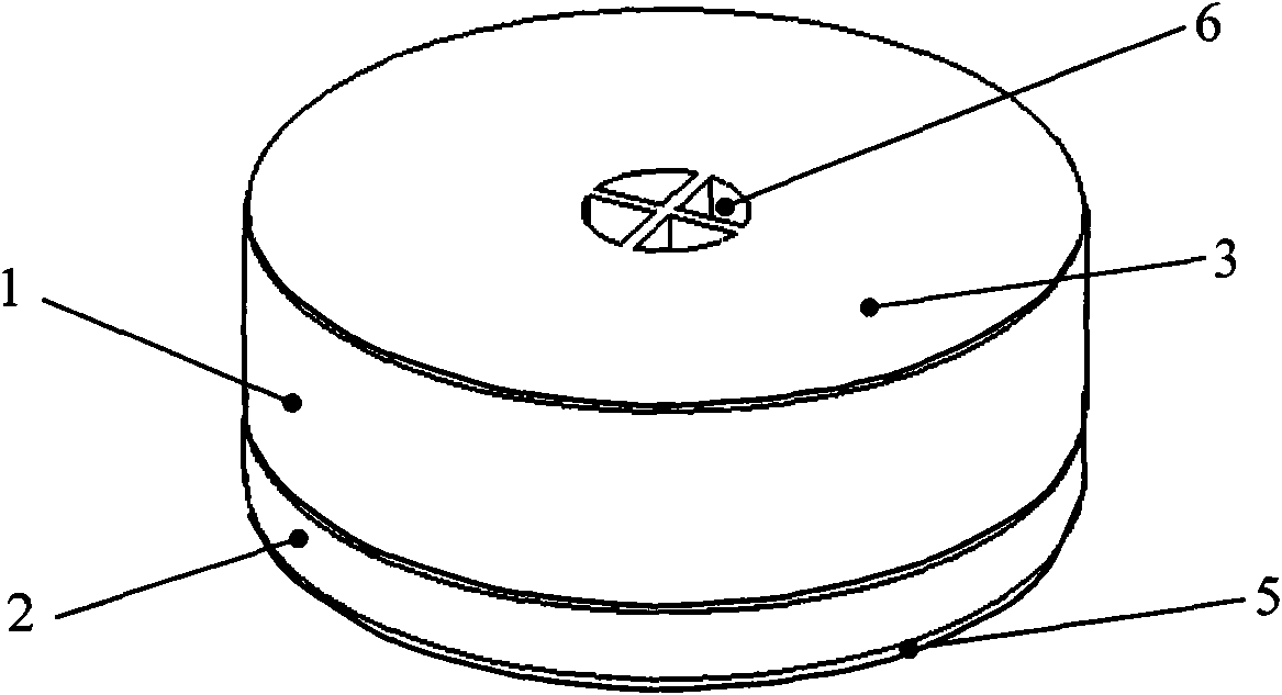
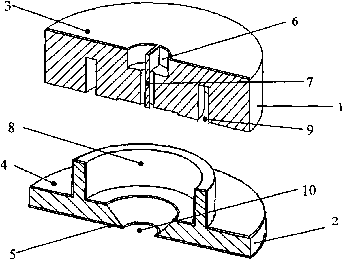
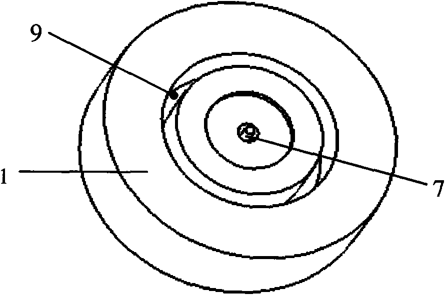
[0013] Such as Figure 1~4 As shown, the present invention is provided with upper silicon chip 1 and lower layer silicon chip 2, sputters a layer of gold thin film on upper layer silicon chip 1 upper surface as upper layer electrode 3, is provided with liquid inlet hole 6 on upper layer silicon chip 1, enters A solid needle tip 7 is provided below the liquid hole 6, a ring-shaped positioning hole 9 is provided in the upper silicon wafer 1, and a layer of SiO is grown on the upper surface of the lower silicon wafer 2 by thermal oxidation. 2 The thin film is used as the insulating layer 4, and the upper surface of the lower silicon wafer 2 is provided with a positioning ring 8 which is nested with the ring-shaped positioning hole 9 arranged in the upper silicon wafer 1, and a layer of gold thin film is sputtered on the back of the lower silicon wafer 2 as The control grid 5 is provided with a nozzle outlet 10 in the middle of the lower silicon wafer 2 .

[0014] The solid needl...


PUM


Abstract

The invention provides a self-aligning micro spray nozzle with a control grid and relates to a spray nozzle. The self-aligning micro spray nozzle is provided with an upper layer silicon chip and a lower layer silicon chip, wherein the upper surface of the upper layer silicon chip is provided with an upper layer electrode; the upper layer silicon chip is provided with a liquid inlet; a needle tip is arranged under the liquid inlet; the inside of the upper layer silicon chip is provided with an annular positioning hole; the upper surface of the lower layer silicon chip is provided with an insulating layer and a positioning ring which is sleeve joint with the annular positioning hole in the upper layer silicon chip; the bottom of the lower layer silicon chip is provided with the control grid; and the middle part of the lower layer silicon chip is provided with a spray nozzle outlet.

Description

technical field [0001] The invention relates to a spray head, in particular to a control grid self-alignment micro spray head. Background technique [0002] As a typical non-silicon manufacturing technology, jet printing technology is a supplement to the traditional silicon process. Compared with the traditional photolithographic molding technology, the high-precision micro-jet printing technology has the advantages of low production cost, simple manufacturing process, and a wide variety of substrates that can be printed. It can realize the printing of functional materials, polymers, biological samples, packaging glue and other materials. With the advantages of fine graphic printing, it can be used as a means of printing conventional graphics and images, and it is also one of the most promising manufacturing technologies for the next generation of optoelectronic flexible devices, large-area devices, curved surface devices, optoelectronic packaging, and biological devices. T...

Claims


Application Information

Patent Timeline
Patent Type & Authority Applications(China)
IPC IPC(8): B41J2/14
Inventor 孙道恒王凌云庄根煌徐磊
Owner XIAMEN UNIV
Why Eureka
Try Eureka