Eureka AIR delivers breakthrough ideas for toughest innovation challenges, trusted by R&D personnel around the world.

Orthotic or prosthetic joint device and method for controlling same

A joint and orthopedic technology, applied in the direction of program-controlled manipulators, prostheses, manufacturing tools, etc., to avoid the loss of penetration and guidance

Active Publication Date: 2015-05-06
OTTO BOCK HEALTHCARE IP GMBH & CO KG
View PDF13 Cites 12 Cited by
  • Summary
  • Abstract
  • Description
  • Claims
  • Application Information

AI Technical Summary

Problems solved by technology

This requires a high pump power, which in turn requires a large pump with a large construction volume and a correspondingly large energy storage device

Method used


Image

  • Orthotic or prosthetic joint device and method for controlling same
  • Orthotic or prosthetic joint device and method for controlling same
  • Orthotic or prosthetic joint device and method for controlling same

Examples


Embodiment Construction

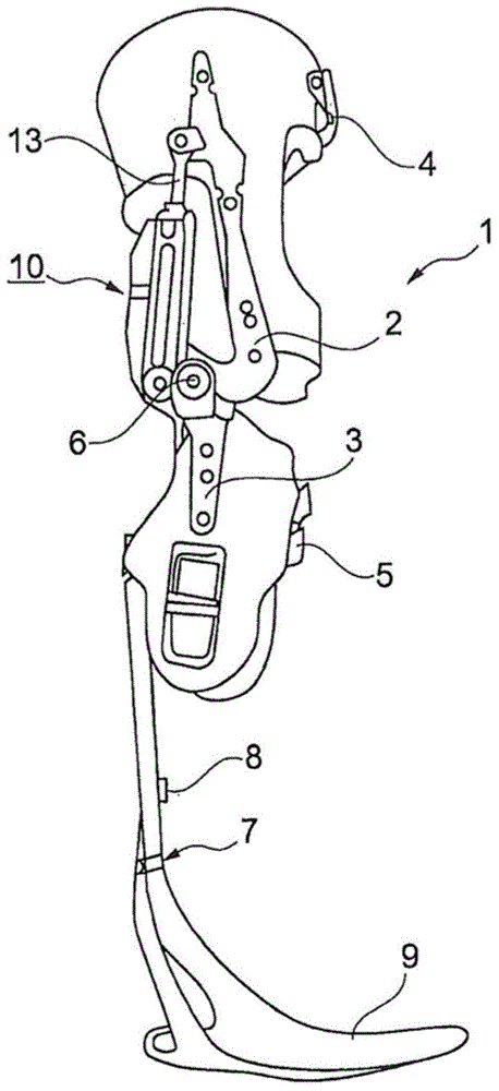
[0049] figure 1 shows an orthopedic joint device as part of a leg orthosis. The joint device 1 has an upper part 2 and a lower part articulated thereon. Fastening devices 4 , 5 , which are designed as cups or sleeves, are arranged on the upper part 2 and the lower part 3 . In the illustrated embodiment, the cups and sleeves are secured to the upper and lower legs of the user of the orthosis. The upper part 2 is mounted relative to the lower part 3 so as to be pivotable about a pivot axis 6 . Arranged on the lower part 3 is a foot part, on which sensors 7 , 8 can be arranged in order to ascertain the position of the lower part 3 , the force or moment or the speed acting on it. A hydraulic unit 10 is arranged between the upper part 2 and the lower part 3 , which will be described in detail later. Arranged in the hydraulic unit 10 is a piston rod 13 , by means of which a displacement of the upper part 2 relative to the lower part 3 about the axis of rotation 6 is effected. T...


PUM


Abstract

The invention relates to an orthotic or prosthetic joint device with an upper part (2) and a lower part (3) arranged in a hinged manner on the latter, and fastening means (4, 5) for securing the joint device (1) on a user, with at least one hydraulics unit (10) between the upper part (2) and the lower part (3), which hydraulics unit (10) has a piston (12) that is movable in a housing (11) with an extension chamber (14) and a flexion chamber (15) and that is coupled to the upper part (2) or the lower part (3), and which hydraulics unit (10) is assigned a pressure supply device (20) with a pump (21) and a pressure accumulator (23) via which the piston (12), controlled by a control device (60), is subjected to a pressure, wherein the pump (21) can be operated in generator mode, the pressure accumulator (23) can be coupled drivingly to the pump (21), and the hydraulic fluid can be conveyed by the pressure accumulator (23) through the pump (21) to the hydraulics unit (10).

Description

technical field [0001] The invention relates to an orthopedic or prosthetic joint device having an upper part and a lower part arranged in an articulated manner on the upper part and a method for controlling an orthopedic or prosthetic joint device and a method for controlling an orthopedic or prosthetic joint device. Fixing devices for fixing the joint on the user, the orthopedic or prosthetic joint having at least one hydraulic unit between the upper part and the lower part, the at least one hydraulic The unit has a piston in a housing, which is coupled to the upper part or the lower part, and a pressure supply is assigned to the hydraulic unit, by means of which the piston is acted upon with pressure. Background technique [0002] The purpose of an orthopedic or prosthetic device is to balance obstacles in athletic equipment. Patients requiring orthopedic or prosthetic joint devices on the lower limbs require increased concentration expenditure and increased energy expen...

Claims


Application Information

Patent Timeline
Patent Type & Authority Applications(China)
IPC IPC(8): A61F2/64A61H3/00A61F2/68B25J9/00A61F2/60A61F2/70A61F2/74A61F2/76
CPCA61F2/60A61F2/64A61F2002/704A61F2002/708A61F2002/7625A61F2002/7635A61F2002/7645A61F2002/7655A61H1/024A61H3/00A61H2003/001A61H2201/0165A61H2201/1246A61H2201/165A61H2201/5002A61H2201/5061A61H2201/5069A61H2201/5079A61F5/0123A61F2/70A61F2/741A61F2/74A61F2/748A61F2/68
Inventor C·威尔M·普赖斯S·扎林C·哈特曼
Owner OTTO BOCK HEALTHCARE IP GMBH & CO KG
Why Eureka
Eureka Blog
Learn More