Reciprocating manipulator for machining punching machine

A reciprocating, manipulator technology, applied in the field of mechanical processing, can solve the problems of workers' safety cannot be guaranteed, low degree of automation, high labor intensity, etc., and achieve the effect of easy promotion and use, high degree of automation and low production cost

Inactive Publication Date: 2015-05-13
XIAN ZHIYUE ELECTROMECHANICAL TECH
View PDF0 Cites 8 Cited by
  • Summary
  • Abstract
  • Description
  • Claims
  • Application Information

AI Technical Summary

Problems solved by technology

Using manual methods to remove workpieces has problems such as high labor intensity, ...

Method used


Image

  • Reciprocating manipulator for machining punching machine
  • Reciprocating manipulator for machining punching machine
  • Reciprocating manipulator for machining punching machine

Examples


Embodiment Construction

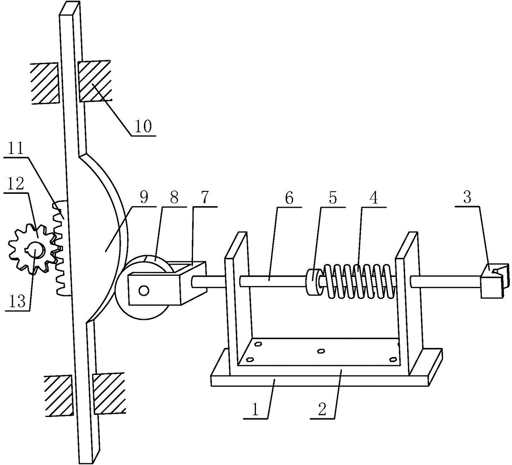
[0017] Such as figure 1 The shown reciprocating manipulator for punch processing includes a base 1, a U-shaped bracket 2 fixed and installed on the upper side of the base 1 by a plurality of bolts for supporting the push rod 6 to move left and right in the horizontal direction, slidingly arranged on the mounting The disc cam 9 used to drive the push rod 6 to slide forward on the frame 10, the return spring 4 used to drive the push rod 6 to reset, and the power shaft 13 used to provide power; the middle part of the push rod 6 is fixed A spring stopper 5 is provided, and the return spring 4 is arranged between the spring stopper 5 and the U-shaped bracket 2, and one end of the push rod 6 is welded or screwed and fixedly installed with a handle for removing the workpiece from the punching machine for processing. Elastic pusher 3, the other end of the push rod 6 is welded or fixed with a roller frame 7, and the roller frame 7 is rotated by a pin to install a roller that cooperates...


PUM


Abstract

The invention discloses a reciprocating manipulator for machining a punching machine. The reciprocating manipulator comprises a base, a U-shaped bracket, a disc-shaped cam, a return spring and a power shaft, wherein a spring stopper is fixed in the middle of a push rod; the return spring is arranged between the spring stopper and the U-shaped bracket; an elastic pushing hand for moving out a punching machine machining workpiece is fixed and mounted at one end of the push rod; a roller frame is fixed at the other end of the push rod; a roller fitting the disc-shaped cam for use and used for reducing the frictional force is rotationally mounted in the roller frame through a pin shaft; a rack is fixed at the back side of the disc-shaped cam; and a gear engaged to the rack to form a gear rack transmission pair is fixed and mounted at the end of the power shaft. The reciprocating manipulator has the characteristics of reasonable design, simple structure, convenience for operation, high automation degree, long service life, wide application range, low production cost and convenience for promotion and application.

Description

technical field [0001] The invention belongs to the technical field of machining, and relates to a manipulator, in particular to a reciprocating manipulator used in conjunction with a punch press. Background technique [0002] Stamping refers to the use of molds to make metal sheets into various sheet-shaped parts, shells, and container workpieces on a punching machine, or to make pipe fittings into various tubular workpieces. In national production, compared with traditional mechanical processing, the stamping process has the advantages of saving materials and energy, high efficiency, low technical requirements for operators, and the ability to produce products that cannot be achieved by mechanical processing through various mold applications. Therefore, Its use is more and more extensive. After the punch press completes the stamping process, all kinds of processed workpieces need to be removed in time. At present, manual methods are widely used to remove workpieces, that...

Claims


Application Information

Patent Timeline
IPC IPC(8): B21D45/02
Inventor 黄冰
Owner XIAN ZHIYUE ELECTROMECHANICAL TECH
Why Eureka
Try Eureka