Machining device for workpiece clamping

A processing device and clamping device technology, applied in metal processing, metal processing equipment, manufacturing tools, etc., can solve the problems of unstable transmission and high equipment cost, and achieve the effects of avoiding workpiece wear, low cost, and ensuring stability

Inactive Publication Date: 2015-05-13
CHONGQING CHAOLIAN IND
View PDF0 Cites 4 Cited by
  • Summary
  • Abstract
  • Description
  • Claims
  • Application Information

AI Technical Summary

Problems solved by technology

[0003] The purpose of the present invention is to provide a processing device for workpiece clamping to solve the p

Method used


Image

  • Machining device for workpiece clamping
  • Machining device for workpiece clamping

Examples


Embodiment Construction

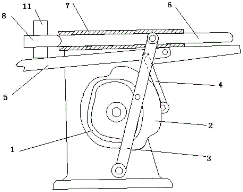
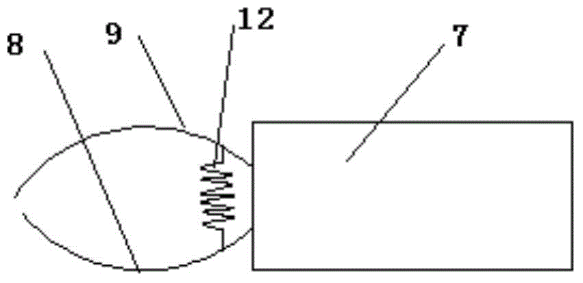
[0013] The reference signs in the description of the drawings are: first cam mechanism 1, second cam mechanism 2, rotating swing lever 3, push-pull control lever 4, support plate 5, sliding clamping device 6, guide rod 7, left clamping body 8 , right clip body 9, workpiece 10, extension spring 11.

[0014] Such as figure 1 , figure 2 As shown, the technical solution provides a processing device for workpiece clamping, including a frame, a transmission device and a control device, and the transmission device includes a first cam mechanism 1, a second cam mechanism 2, a rotating swing rod 3, Push-pull control rod 4, support plate 5 and sliding clamping device 6, a guide rod 7 is fixedly installed horizontally on the frame, sliding clamping device 6 is slidably connected inside the guide rod 7, and one end of the sliding clamp body is connected with a left clamp Body 8 and right clamp body 9, left clamp body 8 and right clamp body 9 are hinged and formed, and are connected by ...


PUM


Abstract

The invention relates to a machining device for workpiece clamping. The machining device comprises a machine frame, a conveying device and a control device. The conveying device comprises two cam mechanisms, a rotating swinging rod, a pushing-pulling control rod, a supporting plate and a sliding clamping device. A guiding rod is horizontally arranged on the machine frame. A sliding clamping body is connected into the guiding rod in a sliding mode. One end of the sliding clamping body is provided with a left clamping body and a right clamping body which are hinged and are connected through a compressed spring. The middle portion of the rotating swinging rod is connected with a first cam. The two ends of the rotating swinging rod are hinged to the machine frame and the sliding clamping device. A supporting plate is placed below the sliding clamping device. The right end of the supporting plate is hinged to the machine frame. The middle portion of the supporting plate is hinged to the pushing-pulling control rod. The middle portion of the pushing-pulling control rod is hinged to the machine frame. The lower end of the pulling-pushing control rod is connected to a second cam mechanism. The problem that during an existing workpiece clamping conveying process, conveying is not stable, or equipment cost is high is solved.

Description

technical field [0001] The invention relates to workpiece processing equipment, in particular to a processing device for workpiece clamping. Background technique [0002] In workpiece production, processing and manufacturing, workpieces need to be transferred between every two processing stations. At present, CNC equipment or transmission belts are generally used to transfer workpieces. As for the CNC sorting method, since such equipment often needs to be debugged and the price is high, it is usually not suitable for small processing plants. For the way of conveyor belt, there are many uncertain factors in the transmission of workpieces in the conveyor belt, especially for circular workpieces. During the transmission process, if the workpieces are not well positioned, the workpieces will roll around and collisions will occur between workpieces. , mutual friction, etc., which may cause greater wear on the workpiece, thereby affecting the quality of the workpiece. Contents ...

Claims


Application Information

Patent Timeline
IPC IPC(8): B23Q7/04B23Q41/02
CPCB23Q7/00B23Q7/04
Inventor 黄政
Owner CHONGQING CHAOLIAN IND
Why Eureka
Try Eureka