
Hot mark stamping mechanism, hot mark stamping system and hot mark stamping method of hot mark stamping system

A technology of driving mechanism and rotating mechanism, which is applied in printing machines, rotary printing machines, printing, etc., can solve the problem of not being able to meet the requirements of thermal printing color temperature and precision, and unable to control the position of thermal marking and line body, thermal printing, etc. The heating temperature of the marking machine cannot be well controlled, etc., so as to achieve the effect of good marking effect, ensuring accuracy and meeting the requirements of precision

Active Publication Date: 2015-05-13
苏州启成精密工业有限公司
View PDF10 Cites 2 Cited by
  • Summary
  • Abstract
  • Description
  • Claims
  • Application Information

AI Technical Summary

Problems solved by technology

[0003] Most of the current line markings are manually operated, and the heating temperature of the thermal marking machine cannot be well controlled, which cannot meet the temperature and accuracy requirements of the thermal printing color; nor can it control the thermal marking position and the line position, and cannot be accurate. Engraving, the engraving effect is relatively poor, and it is easy to cause damage to the wire body, which cannot well meet the actual application requirements

Method used


Image

  • Hot mark stamping mechanism, hot mark stamping system and hot mark stamping method of hot mark stamping system
  • Hot mark stamping mechanism, hot mark stamping system and hot mark stamping method of hot mark stamping system
  • Hot mark stamping mechanism, hot mark stamping system and hot mark stamping method of hot mark stamping system

Examples


Embodiment Construction

[0048] Preferred embodiments of the present invention will be described in detail below in conjunction with the accompanying drawings.

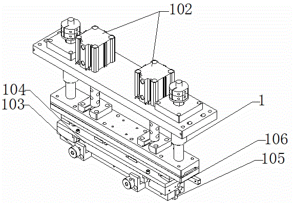
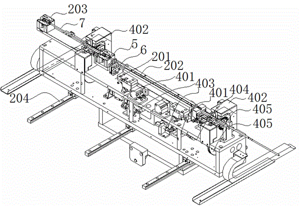
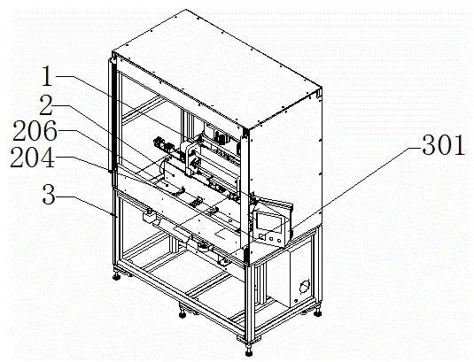
[0049] In order to achieve the purpose of the present invention, in some embodiments, such as figure 1As shown, the thermal marking mechanism includes a frame body 101 and a thermal marking device arranged on the frame body. The thermal marking device includes a first driving mechanism 102, a knife mold device and at least one thermal marking position 103. The thermal marking device The position 103 is located at the bottom of the die cutting device, and the die die device is also provided with a thermocouple sensor (not shown), and the thermocouple sensor is used to control the heating temperature of the die die device, and the thermocouple sensor senses After the die-cutting device is heated to a suitable temperature, the first driving mechanism 102 drives the die-cutting device to move up and down, so as to mark on the wire body 7 through ...


PUM


Abstract

The invention discloses a hot mark stamping mechanism, a hot mark stamping system and a hot mark stamping method of the hot mark stamping system. The hot mark stamping mechanism comprises a frame and a hot mark stamping device arranged on the frame. The hot mark stamping device comprises a first driving mechanism, a knife mold device and at least one hot mark stamping site, the hot mark stamping sites are arranged at the bottom of the knife mold device, and a thermocouple sensor is further arranged on the knife mold device and used for controlling the heating temperature of the knife mold device. After the thermocouple sensor senses that the knife mold device is heated to a proper temperature, the knife mold device moves vertically under the effect of the first driving mechanism, so that mark stamping is performed on a line through the hot mark stamping sites. The hot mark stamping system comprises the hot mark stamping mechanism and further comprises a line feeding mechanism and a rack. The hot mark stamping method is applied to the hot mark stamping system.

Description

technical field [0001] The invention belongs to the field of thermal marking, and in particular relates to a thermal marking mechanism, a thermal marking system and a thermal marking method thereof. Background technique [0002] According to the assembly requirements of general wire workpieces, some indicator lines need to be engraved on the surface when leaving the factory, so as to facilitate accurate use during later assembly and use. [0003] Most of the current line markings are manually operated, and the heating temperature of the thermal marking machine cannot be well controlled, which cannot meet the temperature and accuracy requirements of the thermal printing color; nor can it control the thermal marking position and the position of the line body, and cannot be accurate. Engraving, the engraving effect is relatively poor, and it is easy to cause damage to the wire body, which cannot well meet the needs of practical applications. Contents of the invention [0004...

Claims


Application Information

Patent Timeline
Patent Type & Authority Applications(China)
IPC IPC(8): B41F17/10
Inventor 周益峰张毅陈洋蒋大成
Owner 苏州启成精密工业有限公司
Learn More