Novel hand-slip preventive brake pull rod for railway truck

A technology for railway wagons and brake rods, which is applied in the railway braking system, the operating mechanism of railway vehicle brakes, railway car body parts, etc. It can solve the problems of affecting driving safety and breaking of hand brake parts, etc., and achieve integrity Good, beautiful appearance, and the effect of improving the degree of commercialization

Active Publication Date: 2015-05-13
CRRC MEISHAN
View PDF6 Cites 2 Cited by
  • Summary
  • Abstract
  • Description
  • Claims
  • Application Information

AI Technical Summary

Problems solved by technology

When the vehicle implements the hand brake after the wind brake is applied, the brake cylinder piston reaches the maximum stroke and all the tile wheels wear to the limit. When the vehicle hand brake lever chain, hand brake lever, hanger, etc. When the parts are out of tolerance, wrongly installed, or misplaced, the tail of the guide rod of the hand brake lever will come out of the guide frame and be stuck and cannot be relieved, resulting in the breakage of the hand brake parts or the failure of the brake brake; and the hand brake of the existing truck The dynamic tie rod is often broken at the tail of the 600mm long reinforcing rod due to stress concentration and fatigue at the sudden change in the cross section of the tail, which affects driving safety

Method used


Image

  • Novel hand-slip preventive brake pull rod for railway truck
  • Novel hand-slip preventive brake pull rod for railway truck
  • Novel hand-slip preventive brake pull rod for railway truck

Examples


Embodiment Construction

[0021] The present invention will be described in detail below with reference to the accompanying drawings.

[0022] In order to make the objectives, technical solutions and advantages of the present invention clearer, the present invention will be further described in detail below with reference to the accompanying drawings and embodiments. It should be understood that the specific embodiments described herein are only used to explain the present invention, but not to limit the present invention.

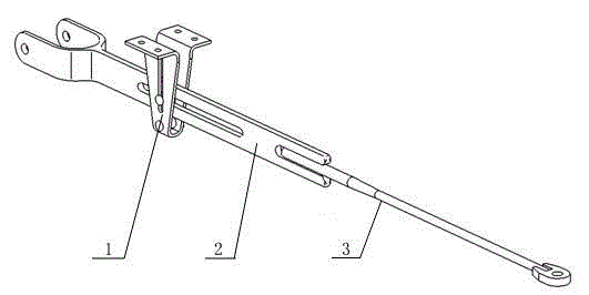
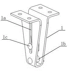
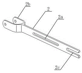
[0023] like Figure 1-5 As shown in the figure, a new type of anti-drop hand brake pull rod for railway freight cars includes a pull-off guide frame 1, a pull rod head 2 and a pull rod 3. A guide groove 1a is provided on the anti-falling guide frame 1 along its vertical direction, and the vertical freedom of the tie rod head is released through the guide groove. The head 2 is provided with an anti-separation groove 2a along its horizontal direction. The tie rod head 2 is placed o...


PUM


Abstract

The invention discloses a novel hand-slip preventive brake pull rod for a railway truck. The novel hand-slip preventive brake pull rod comprises a hand-slip preventive guide frame, a pull rod head and a pull rod. Guide grooves are formed in the hand-slip preventive frame along the vertical direction of the hand-slip preventive frame, a carrier roll is arranged on the lower portion of the hand-slip preventive frame, a hand-slip preventive groove is formed in the pull rod head along the horizontal direction of the pull rod head, the pull rod head is arranged on the carrier roll and is connected with the hand-slip preventive guide frame by a hand-slip preventive pin which penetrates the guide grooves and the hand-slip preventive groove, and an end of the pull rod is fixedly connected with a tail groove of the pull rod head. The novel hand-slip preventive brake pull rod has the advantages that problems of clamping stagnation due to the fact that an existing hand brake pull rod for a railway truck slips out of an existing carrier roll at a sudden sectional change position of round steel and breakage of the existing hand brake pull rod due to fatigue and stress concentration at a sectional sudden change position of the tail of the existing hand brake pull rod can be effectively solved by the aid of the novel hand-slip preventive brake pull rod; the pull rod head still can be fixed onto the hand-slip preventive guide frame by the aid of the hand-slip preventive pin even if the tail of the pull rod is accidentally broken, a rod body of the integral pull rod head can be supported by the carrier roll without falling off, and accordingly the driving safety can be guaranteed.

Description

technical field [0001] The invention relates to the technical field of railway freight car braking, in particular to a novel anti-drop hand brake lever for railway freight cars driven by a movable pulley. Background technique [0002] At present, most of the handbrake levers of the handbrake devices of the existing railway freight cars in our country adopt two 600mm long reinforcing rods and the handbrake levers in a side-by-side welding structure, and are guided by the handbrake lever hanger. When the vehicle implements the wind brake and then implements the hand brake, the brake cylinder piston reaches the maximum stroke and all the wheels wear to the limit and other extreme conditions, when the vehicle hand brake lever chain, hand brake lever, hanger, etc. When the parts are out of tolerance, wrongly installed, or misplaced, the tail of the handbrake lever guide rod will come out of the guide frame and will be stuck and cannot be relieved, resulting in the breakage of the...

Claims


Application Information

Patent Timeline
Patent Type & Authority Applications(China)
IPC IPC(8): B61H13/02
CPCB61H13/02
Inventor 秦啸陶斌周炯杨清帆张雄王璞江明星肖八励郑欣欣刘艳
Owner CRRC MEISHAN
Why Eureka
Try Eureka