Light-weighted composite momentum flywheel for satellite and manufacture method thereof

A composite material, lightweight technology, applied in the direction of aerospace vehicle guidance devices, etc., can solve the problems of increasing flywheel cycle and cost, the impact of flywheel dynamic balance performance, and difficulty in meeting the requirements for mass use of lightweight satellite platforms, to achieve increased balance. Stability, meeting attitude control requirements, and excellent damping performance

Active Publication Date: 2015-05-13
SHANGHAI COMPOSITES SCI & TECH CO LTD +1
View PDF4 Cites 14 Cited by
  • Summary
  • Abstract
  • Description
  • Claims
  • Application Information

AI Technical Summary

Problems solved by technology

[0004] However, since the hub, spokes and rim of the flywheel are mechanically connected by fasteners, the gap between the fasteners and each part of the flywheel and the unevenness of the overall weight distribution of the flywheel have a great influence on the dynamic unbalance After assembly, a large number of tests to adjust the dynamic balance are required, and the adjustment time is often much longer than the processing cycle, so the cycle and cost of flywheel development are greatly increased, and it is difficult to meet the batch use requirements of lightweight satellite platforms and patterns
Moreover, the fasteners will loosen to a certain extent during the acceleration, deceleration and vibration of the flywheel. The slight asymmetric weight formed by these looseness on the circumference will have a great impact on the overall dynamic balance performance of the flywheel

Method used


Image

  • Light-weighted composite momentum flywheel for satellite and manufacture method thereof
  • Light-weighted composite momentum flywheel for satellite and manufacture method thereof
  • Light-weighted composite momentum flywheel for satellite and manufacture method thereof

Examples


Embodiment 1

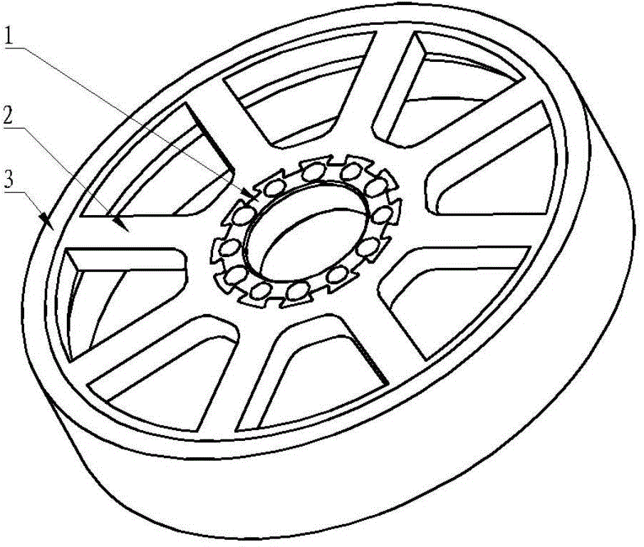
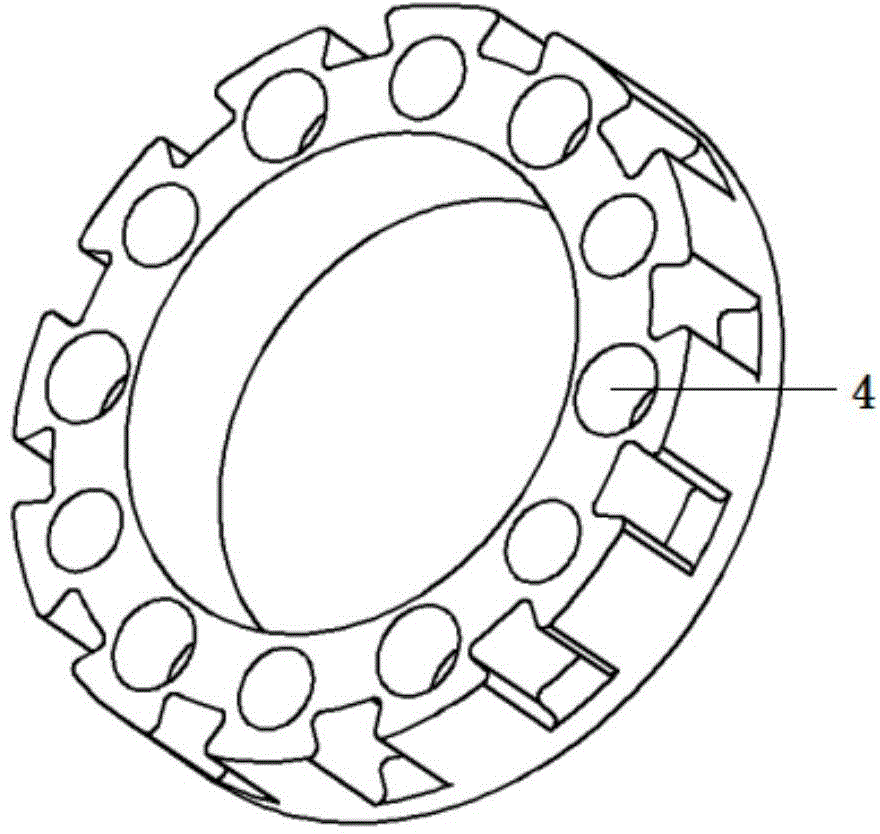
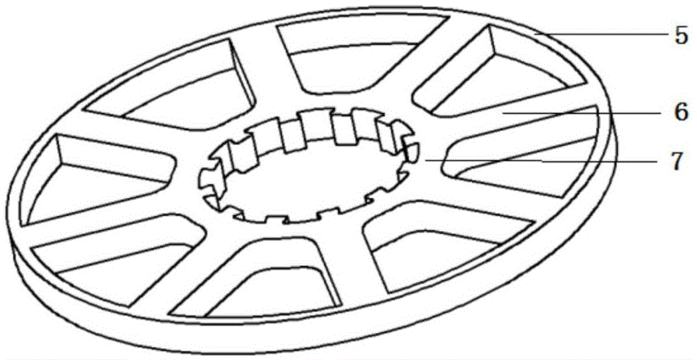
[0043] This embodiment combines figure 1 , 2 , 3 for further explanation, the satellite that the present embodiment relates to is used the lightweight composite material momentum flywheel, comprises wheel hub 1, wheel spoke 2, wheel rim 3 successively (see figure 1 ), the middle of the hub 1 is provided with a middle hole 4, and the spokes include outer spokes 5, spokes 6, and inner spokes 7; the material of the hub is 7075 aluminum alloy (see figure 2 ), the outer circumference is provided with a connecting groove, the groove is trapezoidal, and the inclination angle of the side is 15°; the spoke (see image 3 ) is a carbon fiber composite material. The inner spokes and rectangular spokes that are in contact with the hub are laid layer by layer with integrally cut T300 / epoxy resin prepreg cloth. The outer spoke ring in contact with the rim is wound in full axial direction with T700 / epoxy resin prepreg; the rim (see Figure 4) is made of 0Cr18Ni9Ti, and the internal parts ...

Embodiment 2

[0053] This embodiment provides a lightweight composite momentum flywheel for satellites and its preparation method. The technical solution is a preferred example of implementation 1. The only improvements are:

[0054] Step 3: The inner surface of the wheel rim is subjected to sandblasting and roughening treatment with high-pressure fine sand: the size of the fine sand is 0-100 mesh, the sandblasting pressure is 0.8MPa, and the spraying time is 20 minutes;

[0055] In step 4, heat the mold to about 120°C for 0.5h, slowly pressurize to 0.3MPa, release the pressure, then increase the pressure to 1.2MPa, and at the same time raise the temperature to 180°C, and cure for 6h, so that the aluminum alloy hub, spoke and The rim is co-solidified into one.

[0056] The number of spokes of the prepared flywheel is 8; the length and width of the vertical section of the spokes are 20mm and 10mm respectively; The ratio between them is 4:5:6.

Embodiment 3

[0058] This embodiment provides a lightweight composite momentum flywheel for satellites and its preparation method. The technical solution is a preferred example of implementation 1. The only improvements are:

[0059] Step 3: The inner surface of the wheel rim is subjected to sandblasting and roughening treatment with high-pressure fine sand: the size of the fine sand is 0-100 mesh, the sandblasting pressure is 0.5MPa, and the spraying time is 15 minutes;

[0060] In step 4, heat the mold to about 100°C for 0.5h, slowly pressurize to 0.2MPa, release the pressure, then increase the pressure to 1MPa, and at the same time raise the temperature to 180°C, and cure for 4.5h, so that the hub, spoke and rim co-cured into one.

[0061] The number of spokes of the prepared flywheel is 10; the length and width of the vertical section of the spokes are 10mm and 10mm respectively; The ratio between them is 4:5:6.


PUM


Abstract

The invention provides a light-weighted composite momentum flywheel for satellite and manufacture method thereof. From inside to outside, the flywheel is provided with a hub, spokes and a rim. Connecting grooves are formed in the periphery rim of the juncture of the hub and the spokes, centre holes are formed at the middle of the periphery. A plurality of mounting holes are formed between the groves and the centre holes. The spokes comprises a outer spoke ring, wire spokes and an inner spoke ring. The outer spoke ring is connected with the rim, the wire spokes are multiple, and the inner spoke ring is connected with the hub. Connecting humps are formed in the inner spoke ring. Annular humps are formed in the inside wall of the rim. The hub and the spokes are connected with the grooves and the humps structure in a meshing and co-curing mode. The outer spoke ring is connected with the outer rim in a bonding and close-fitting mode. The bottom of the spokes are arranged on the annular humps in the inside wall of the rim. The light-weighted composite momentum flywheel for satellite and manufacture method thereof have the advantages that the light carbon fiber composite with high strength and good damping property is used. A faster connection mode is replaced by the connection mode of close-fitting and bonding. The passive weight of the flywheel is reduced greatly, the damping capacity of the flywheel is enhanced greatly, and the manufacturing cycle is shortened.

Description

technical field [0001] The invention relates to a spacecraft structure and mechanism, in particular to a lightweight composite material momentum flywheel for a satellite and a preparation method thereof. Background technique [0002] The flywheel is an important part for outputting angular inertia. At present, the momentum flywheels of satellites are all one-piece structures, and are made of metal materials such as high-strength steel or aluminum alloy. Although this structural form can meet the momentum requirements, the mass of the wheel body is heavy, and a large amount of materials are used on the hub and spokes. These materials contribute little to the moment of inertia and belong to negative mass. Due to the structural characteristics of the metal material itself, the one-piece flywheel that is integrally processed with a metal block has poor damping performance. Once the flywheel is disturbed during its rotation, it will take a long time to recover, which is extremel...

Claims


Application Information

Patent Timeline
Patent Type & Authority Applications(China)
IPC IPC(8): B64G1/28
Inventor 沈峰潘韵熊美居建国唐宏亮李涛
Owner SHANGHAI COMPOSITES SCI & TECH CO LTD
Why Eureka
Try Eureka