
Temporary support of hydraulic supports in excavation work

A technology of excavation work and hydraulic support, which is applied in the field of excavation construction work, timely support hydraulic support for excavation work, and coal mine machinery and equipment to achieve the effect of facilitating smooth frame removal, strengthening protection, and preventing roof caving

Active Publication Date: 2017-06-09
安徽恒源煤电股份有限公司
View PDF8 Cites 1 Cited by
  • Summary
  • Abstract
  • Description
  • Claims
  • Application Information

AI Technical Summary

Problems solved by technology

Before moving the frame, lower the hydraulic support first, and one end of the lifting cylinder located at the front of the base protrudes to support the upper surface of the lifting support plate, and exerts pressure on the lifting support plate, and the bottom lifting support plate transmits the pressure to the bottom of it The bottom plate of the roadway, so that the front end of the base of the hydraulic support is lifted up, which reduces the resistance between the base and the bottom plate of the roadway, and solves the problem that the front end of the base is difficult to move when the frame is moved, which is convenient for moving the frame smoothly; It will not damage the floor of the roadway, so there is no need for manual cleaning

Method used


Image

  • Temporary support of hydraulic supports in excavation work
  • Temporary support of hydraulic supports in excavation work
  • Temporary support of hydraulic supports in excavation work

Examples


Embodiment 1

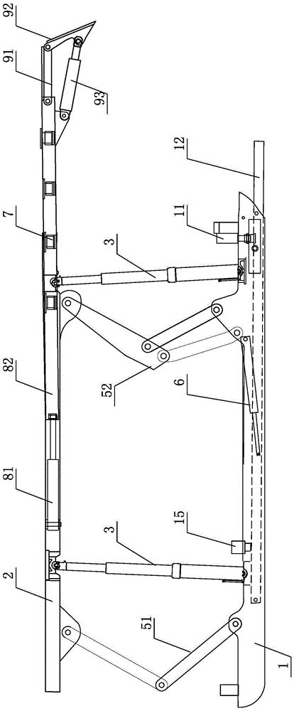
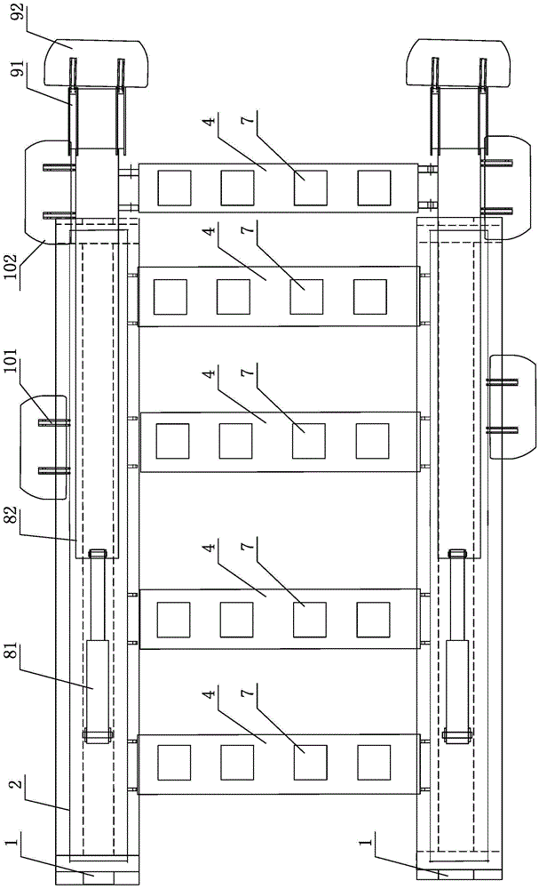
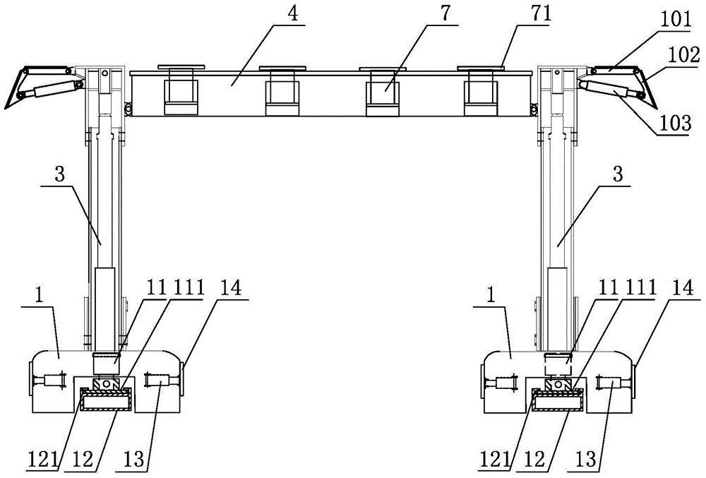
[0028] Such as figure 1 , figure 2 and image 3 As shown, the excavation working face of the present embodiment supports the hydraulic support in time and includes a protective top beam 4 and two longitudinal load-bearing structures respectively arranged on the left and right sides of the protective top beam 4; each longitudinal load-bearing structure includes a longitudinal load-bearing top beam 2. The base 1, the hydraulic support column 3 connecting the longitudinal load-bearing top beam 2 and the base 1 and the load-bearing top beam stabilization mechanism, that is, the two-bar mechanism 51 and the four-bar linkage mechanism 52; the protective top beam 4 is connected to the longitudinal load-bearing top beam 2 And fix the relative position between the two longitudinal bearing structures. Such as image 3 and Figure 4 As shown, wherein, the cross-section of the base 1 is in the shape of a groove opening downwards, and when the excavation work is being carried out, the...

Embodiment 2

[0048] The second embodiment is basically on the basis of the first embodiment, and the excavation work face is set up in groups at the front and rear of the temporary support hydraulic supports.

[0049] The first setting method of Embodiment 2: each excavation working face set at the front and back is independent of the temporary support hydraulic supports, that is, the lifting base device and the pushing cylinder of each hydraulic support are independent, and the lifting base and moving cylinder of each hydraulic support are independent. The racking process is the same as that in Embodiment 1, and will not be illustrated or described in detail here.

[0050] The second setting method of Embodiment 2: such as Figure 5 and Figure 6 As shown, the rear end of the bottom-lifting support plate 12 of the previous excavation work face and the time-supporting hydraulic support is hingedly connected with the front end of the bottom-lift support plate 12 of the back excavation work...


PUM


Abstract

The invention discloses a temporary support hydraulic support for a tunneling working face. The temporary support hydraulic support for the tunneling working face comprises a protective ejection beam, two longitudinal bearing structural bodies arranged on the left side and the right side of the protective ejection beam, a front protective device and a side protective device. Each longitudinal bearing structure body comprises a longitudinal bearing top beam, a base and supporting stand columns. The cross section of each base is in the shape of a groove with a downward opening. Each base is provided with a base lifting device. Each base lifting device comprises a base lifting oil cylinder and a base lifting supporting plate. Each base lifting oil cylinder is vertically installed on the front portion of the corresponding base. Each base lifting supporting plate is arranged in the groove of the corresponding base. A pushing oil cylinder is arranged between each base lifting supporting plate and the base. The protective top beam is provided with a supporting and loading oil cylinder pointing to a tunnel roof. By the adoption of the temporary support hydraulic support for the tunneling working face, base lifting and self movement of the hydraulic support are achieved, the roof supporting capacity is high, all-directional safety protection is achieved, a safe working environment is created for mine coal roadway fully-mechanized tunneling construction personnel, and the tunneling efficiency and the footage level are improved.

Description

technical field [0001] The invention relates to the technical field of coal mine excavation, in particular to a hydraulic support for temporary support during excavation work, which is mainly used in the excavation construction operation of coal lanes in coal mines, and belongs to coal mine mechanical equipment. Background technique [0002] It is extremely important for coal mines to maintain a normal mining relationship. However, coal mining technology has made great progress over the years, and the relative development of tunneling technology is very slow. There are many problems in roadway excavation construction with many people and low efficiency, which has caused tension in many coal mines. Therefore, it is necessary to study and improve the relevant issues of coal mine development and excavation technology, and accelerate the development and excavation speed. The fully mechanized excavation construction of coal mine roadway is a systematic project. To increase the co...

Claims


Application Information

Patent Timeline
Patent Type & Authority Patents(China)
IPC IPC(8): E21D23/04E21D23/16
CPCE21D23/0078E21D23/0095E21D23/04E21D23/08E21D23/16
Inventor 吴新恒郭雪玲郭晓亮李永罗运辉贾继田
Owner 安徽恒源煤电股份有限公司
Learn More