
A kind of circular tube lateral slamming device and its test method

A round pipe and supporting device technology, applied in the field of dynamic test and testing system, can solve the problems of difficulty in analysis and research, uncertainty of damage degree, non-unique impact results, etc., and achieve adjustable span, adjustable pipe specifications, and slamming radius. adjustable effects

Active Publication Date: 2017-01-25
TAIYUAN UNIV OF TECH
View PDF1 Cites 0 Cited by
  • Summary
  • Abstract
  • Description
  • Claims
  • Application Information

AI Technical Summary

Problems solved by technology

Due to the uncertainty of the position where the pipeline ruptures in the actual production accident, and the impact of the wall and other influences during the swinging process, the impact of the pipeline on other pipelines may be at any angle, and the impact situations are various. The impact result is not unique, and the degree of damage is uncertain, which brings great difficulties to analysis and research

Method used


Image

  • A kind of circular tube lateral slamming device and its test method
  • A kind of circular tube lateral slamming device and its test method
  • A kind of circular tube lateral slamming device and its test method

Examples


Embodiment 1

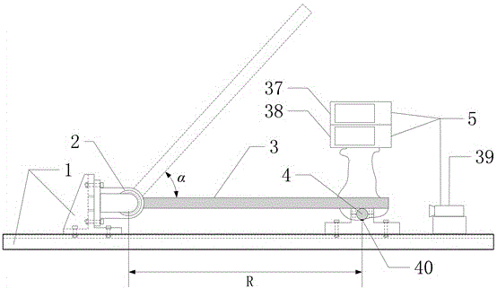
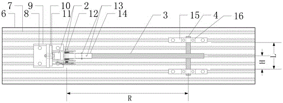
[0071] Such as Figure 10 As shown, when the active tube rotating table 10 is rotated to 0°, the strike plane of the active tube 3 is perpendicular to the driven tube 4, that is, the active tube 3 and the driven tube 4 collide orthogonally. In this case, the active tube 3 does not deflect after colliding with the driven tube 4, but bounces back in the original path.

[0072] Since the driving tube 3 is parallel to the roller shaft clamping groove 30 at the initial moment, and the roller shaft clamping groove 30 is located on the line connecting the two balls 29, that is, the driving tube 3 and the rolling balls 29 are in a horizontal position at the initial moment. In the process of lifting the active tube 3, the ball 29 is in contact with the elevation angle rotating disc 27, and the motor 24 can apply torque to lift the active tube 3. When the active tube 3 is lifted to 60°, the position of the ball 29 is just at the position of the slot 34 of the elevation angle rotating di...

Embodiment 2

[0074] Such as Figure 11 As shown, when the active tube rotating table 10 is rotated to 30°, the strike plane of the active tube 3 and the driven tube 4 are at 60°, that is, the active tube 3 and the driven tube 4 collide at 60°. In this case, the active tube 3 deflects after colliding with the driven tube 4 and pops up to the other side.

[0075] Because the loading device 2 is located on the active tube rotating table 10, when the active tube rotating table 10 rotates, the loading device 2 also rotates, and its working principle does not change. The angle of rotation in the 60° swing plane controls the angle at which the torsion spring 25 rotates. Therefore, changing the elevation angle of the rotating disk 27 can also achieve oblique impact effects at different speeds.


PUM


Abstract

The invention discloses a circular pipe sideward swing impact device and a test method of the circular pipe sideward swing impact device, particularly relates to a testing system of a dynamic test for using a swinging circular pipe to impact on a circular pipe in different angles, and belongs to the field of kinetics experiment devices. The circular pipe sideward swing impact device comprises a driving pipe, a driven pipe, supporting devices, a loading device and measuring devices, wherein the fixed position of a supporting base is controlled to adjust the swing distance of a pipeline and the span of the driven pipe, the swing direction is controlled through a rotating platform, a gear device is driven by a motor to lift the driving pipe up, adjustment of the lifting angle and release of the driving pipe are conducted through an altitude angle rotating disk, and impact results are recorded through the measuring devices, so that experimental observation of sideward swing of the pipeline is achieved.

Description

technical field [0001] The invention relates to a circular tube sideways swinging device and a test method thereof, in particular to a dynamic test system for a swinging circular tube impacting the circular tube at different angles, and belongs to the field of dynamic experimental devices. Background technique [0002] Pressure pipes are widely used in important industrial sectors such as nuclear power plants, petrochemicals, gas and civil buildings, and are mainly used to transport various high-energy (high temperature, high pressure) liquids or gases. Due to the occurrence of accidents, some local cracks and damage may appear on the pressure pipeline, resulting in the leakage of a large amount of harmful liquid or gas. On the one hand, environmental pollution is formed and even explosions and fires are caused, causing huge losses of life and property. Once the pipeline ruptures, the ejected high-pressure fluid will generate a huge reaction force, which will cause the pipel...

Claims


Application Information

Patent Timeline
Patent Type & Authority Patents(China)
IPC IPC(8): G01M7/08
Inventor 路国运杨会伟徐乐赵燕萍
Owner TAIYUAN UNIV OF TECH
Learn More