A device for testing ultrasonic vibration extra-long life fatigue of a material under a high-pressure state

An ultrasonic vibration, ultra-long life technology, applied in the direction of measuring devices, analytical materials, instruments, etc., to achieve the effect of convenient experimental operation and cost reduction

Inactive Publication Date: 2015-05-13
SOUTHWEST JIAOTONG UNIV
View PDF6 Cites 3 Cited by
  • Summary
  • Abstract
  • Description
  • Claims
  • Application Information

AI Technical Summary

Problems solved by technology

[0005] Based on the limitations of the above-mentioned fatigue experiments, the purpose of the present invention is to effectively solve the problem of testing the fatigue performance of materials under high pressure

Method used


Image

  • A device for testing ultrasonic vibration extra-long life fatigue of a material under a high-pressure state
  • A device for testing ultrasonic vibration extra-long life fatigue of a material under a high-pressure state

Examples


Embodiment Construction

[0017] The present invention will be further described in detail below in conjunction with this embodiment, but the embodiments of the present invention are not limited thereto.

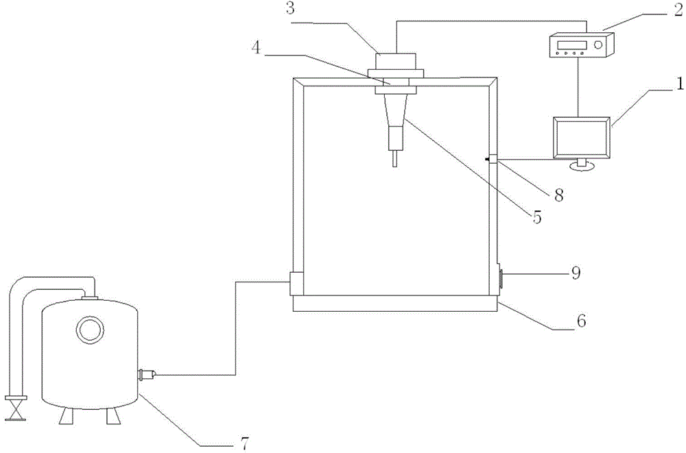
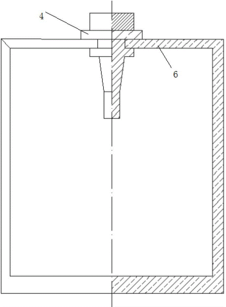
[0018] As shown in the figure, the experimental device includes a material ultrasonic fatigue testing unit and a high-voltage applying device. The ultrasonic fatigue test unit includes a computer system connected in sequence, an energy generator, a piezoelectric ceramic transducer, a horn fixedly connected to the lower end, and an extension rod coaxial with the horn at the output end of the horn. The extension rod is connected to the test piece, and the high-pressure pressure tank is coupled with the horn through screws. The high-pressure pressure tank is equipped with a pressure relief switch and a pressurizing device connected to a pressure pump. The pressurizing device can display the pressure inside the pressure tank through a pressure sensor.

[0019] The working principle of the present inventi...


PUM


Abstract

A device for testing ultrasonic vibration extra-long life fatigue of a material under a high-pressure state is disclosed. A computer system controls electric signals generated by an energy generator (2) to act on a piezoelectric ceramic transducer (3). An amplitude-change pole (5) clamping a sample of the material to be tested is coupled to the piezoelectric ceramic transducer, and can transmit mechanical vibration of the piezoelectric ceramic transducer to the sample of the material to be tested. A sample clamping mechanism of an ultrasonic fatigue testing unit is disposed in a pressure tank (6). A pressure pump (7) is connected to the pressure tank through a pipe. By adoption of the device, the degree of testing difficulty of fatigue performance of materials under high-pressure states is lowered, and satisfied experiment results can be obtained.

Description

Technical field: [0001] The invention relates to an ultrasonic vibration ultra-long life fatigue testing device, in particular to a high frequency and high pressure fatigue testing system. Background technique: [0002] Fatigue is the failure of materials under cyclic loading. In all aspects of modern engineering, such as automobiles, aircraft, ships, rolling stock, railway bridges, nuclear reactors, power generation equipment, etc., most of their main parts and components work under cyclically changing loads, and fatigue is the main form of failure. With the continuous development of industrial technology, various parts and components have been subjected to repeated loads up to 10 times during their service life. 9 ~10 11 Therefore, the high-cycle (ultra-high-cycle) fatigue research of materials has begun to attract the attention of the majority of scientific workers. In the offshore oil drilling platform, because the drilling platform continues to experience fatigue und...

Claims


Application Information

Patent Timeline
Patent Type & Authority Applications(China)
IPC IPC(8): G01N3/02
Inventor 何旭王弘谢卿唐维维周蒙蛟汪奔
Owner SOUTHWEST JIAOTONG UNIV
Why Eureka
Try Eureka