Optical grating and three-dimensional display device

A technology for stereoscopic display devices and gratings, applied in the direction of diffraction gratings, optics, optical elements, etc., can solve the problems of increasing the design and manufacturing costs of stereoscopic displays, unfavorable versatility and maintainability of internal devices, etc., and achieve improved versatility and maintenance performance, improve image quality, and eliminate moiré

Inactive Publication Date: 2015-05-13
SHENZHEN MAGIC EYE TECH CO LTD
View PDF16 Cites 8 Cited by
  • Summary
  • Abstract
  • Description
  • Claims
  • Application Information

AI Technical Summary

Problems solved by technology

This obviously increases the design cost and manufacturing cost of the stereoscopic display, and is not conducive to the versatility and maintainability of the internal components of the stereoscopic display.

Method used


Image

  • Optical grating and three-dimensional display device
  • Optical grating and three-dimensional display device
  • Optical grating and three-dimensional display device

Examples


Embodiment Construction

[0028] The present invention will be described in detail below with reference to the drawings and specific embodiments.

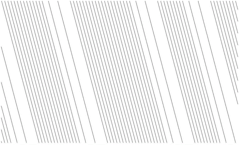
[0029] See Figure 3 to Figure 7 , image 3 It is a schematic diagram of the pattern of the first embodiment of the grating of the present invention. Figure 4 It is a schematic diagram of the second embodiment of the grating of the present invention. Figure 5 It is a schematic diagram of the pattern of the third embodiment of the grating of the present invention. Image 6 It is a schematic diagram of the pattern of the fourth embodiment of the grating of the present invention. Figure 7 It is a schematic diagram of a pattern in which the grating pitch of the micro-optical structure of the third embodiment changes periodically.

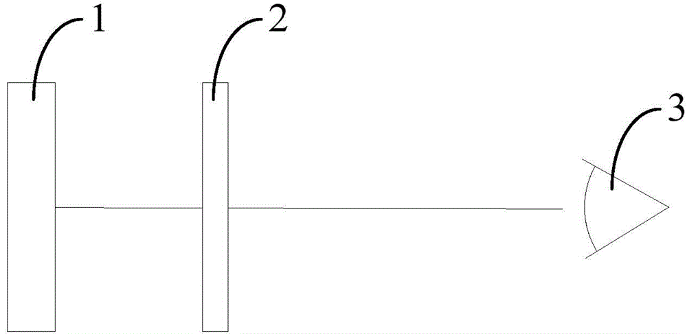
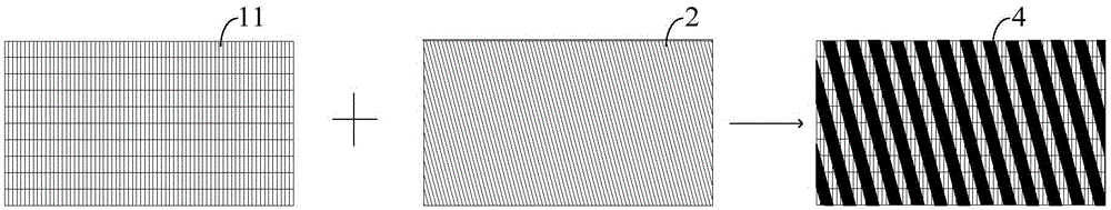
[0030] A grating is used for spreading light to different directions through light splitting to realize three-dimensional display. The grating includes a plurality of micro-optical structures arranged in an array, and at least some of t...


PUM


Abstract

The invention discloses an optical grating and a three-dimensional display device. The optical grating is used for spreading light in different directions through a light splitting effect o realize three-dimensional display; the optical grating comprises a plurality of micro optical structures which are arranged in the form of an array, wherein the grating distances of part of the micro optical structures are different. The three-dimensional display device comprises a display panel and the optical grating; the display panel comprises a plurality of display units which are arranged in the form of the array; the optical grating and the display panel are stacked; an included angle is formed between the inclined direction of the micro optical structures and the diagonal line direction of the display units. The optical grating can be used for effectively eliminating moire patterns and improving the universality and the maintainability of apparatuses in the three-dimensional display device.

Description

Technical field [0001] The present invention relates to the field of stereo display, in particular to gratings and stereo display devices. Background technique [0002] At present, the naked-eye stereoscopic display device is getting more and more attention because it does not need to wear special 3D glasses. The existing naked-eye 3D stereo displays are mainly developed based on binocular parallax, and are mainly raster-type stereo displays. Raster stereo display is a three-dimensional display technology based on the principle of binocular parallax. The binocular disparity means that there is a certain interpupillary distance between the two eyes of a person. When viewing an object, the visual images received by the left eye and the right eye are slightly different. The brain merges the left and right eye images with subtle differences to produce Three-dimensional scenery with a sense of space. [0003] Such as figure 1 As shown, the existing grating-type stereoscopic display i...

Claims


Application Information

Patent Timeline
Patent Type & Authority Applications(China)
IPC IPC(8): G02B5/18G02B27/22
CPCG02B5/1842G02B30/27
Inventor 刘美鸿陈易华
Owner SHENZHEN MAGIC EYE TECH CO LTD
Why Eureka
Try Eureka