
Liquid crystal display device

A liquid crystal display device and display panel technology, which is applied in the directions of instruments, light guides, optics, etc., can solve the problems of high cost, increase product cost, and limit the design of product diversification, so as to reduce production cost, improve the scope of application, save The effect of the grinding process

Active Publication Date: 2015-05-13
TCL CHINA STAR OPTOELECTRONICS TECH CO LTD
View PDF7 Cites 6 Cited by
  • Summary
  • Abstract
  • Description
  • Claims
  • Application Information

AI Technical Summary

Problems solved by technology

[0003] Existing 2.5D display screens can only be applied to small-sized displays, and the appearance of this type of display includes a flat area and a curved area at the edge of the display; the current implementation method of 2.5D display screens is in front of the liquid crystal display ( or the front of the touch screen) is provided with a layer of cover glass, and the edge of the cover glass is processed with a circle of transitional arc surface after grinding process to meet the characteristics of 2.5D display screen, but because of its complicated process and limited size, it increases Product cost and design that limit product diversification
[0004] The process technology of the existing 2.5D display screen is relatively complicated. During the processing process, the glass grinding process will be excessively unsatisfactory, so there will be a certain loss in the yield rate. Therefore, compared with The cost of traditional 2D display screens is relatively high; moreover, the yield rate of large-size glass is extremely low, so this technology is currently not suitable for mass production in the application of large-size display screens. Currently, 2.5D display screens are only It is applied on small-sized displays, and there are certain limitations in the application of product diversification

Method used


Image

  • Liquid crystal display device
  • Liquid crystal display device

Examples


Embodiment Construction

[0018] In order to make the object, technical solution and advantages of the present invention more clear, the present invention will be further described in detail below in conjunction with the accompanying drawings and embodiments. It should be understood that the specific embodiments described here are only used to explain the present invention, not to limit the present invention.

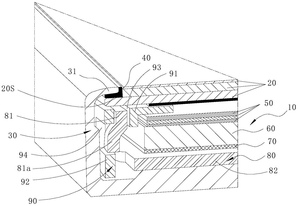
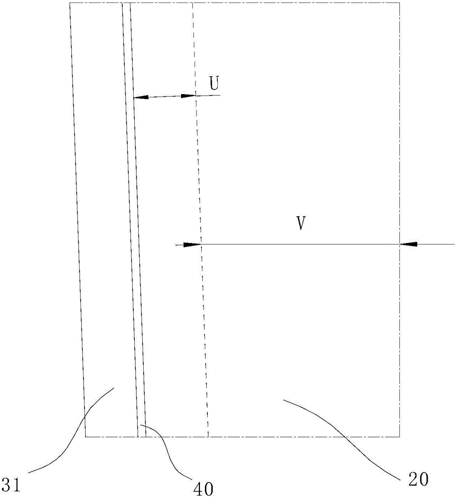
[0019] refer to figure 1 , the liquid crystal display device of the present invention includes a backlight unit 10, a display panel 20 and a first frame 30. The first frame 30 is a decorative frame, specifically a frame integrally formed with the side of the display device. The first frame 30 accommodates the backlight unit 10 and the display panel 20 therein, at least one side wall of the first frame 30 extends toward the middle to form an arc-shaped extension 31 , and the free end of the extension 31 is opposite to the side wall of the display panel 20 set up. The arc-shaped extension part 3...


PUM


Abstract

The invention discloses a liquid crystal display device. The liquid crystal display device comprises a backlight unit, a display panel and a first frame. The first frame contains the backlight unit and the display panel. At least one side wall of the first frame extends to the middle portion, so that an arc-shaped extension portion is formed. The free end of the extension portion is opposite to the side wall of the display panel. According to the liquid crystal display device, the display panel is arranged in the first frame, the side walls of the first frame extend to the middle portion, so that the arc-shaped extension portions are formed, and therefore the display plane and the first frame can be in smooth transition; cover plate glass is omitted, the complicated grinding technology for the cover plate glass is omitted, the limit that a 2.5 D display screen can only be applied to a small-size display device is broken through, the production cost is reduced, and the application range of the display screen is greatly improved.

Description

technical field [0001] The invention relates to the field of display manufacturing, in particular to a liquid crystal display device. Background technique [0002] With the launch of the 2.5D (Dimension) display on the Iphone6, the concept of this display has quickly become one of the hot topics among consumers. 2.5D is mainly different from 3D. Compared with the traditional 2D screen, the 2.5D screen greatly improves the overall visual effect of the screen and the fuselage. At the same time, because there are no sharp edges and corners, the hand feel is also improved. [0003] Existing 2.5D display screens can only be applied to small-sized displays, and the appearance of this type of display includes a flat area and a curved area at the edge of the display; the current implementation method of 2.5D display screens is in front of the liquid crystal display ( or the front of the touch screen) is provided with a layer of cover glass, and the edge of the cover glass is proces...

Claims


Application Information

Patent Timeline
Patent Type & Authority Applications(China)
IPC IPC(8): G02F1/13
CPCG02F1/133606G02F1/133608G02B6/0088G02F1/13G02F1/133317G02B6/005G02B6/0055G02F1/133308G02F1/133512G02F2202/28
Inventor 陈仕祥阙成文
Owner TCL CHINA STAR OPTOELECTRONICS TECH CO LTD
Learn More