Small-diameter collecting pipe branch pipe drawing process tooling

A collection tube and small-diameter technology, which is applied in the field of drawing process tooling for small-diameter manifold branch pipes, can solve the problems of difficulty in ensuring the straightness and surface quality of the main pipe, affecting metal properties, and waste of metal materials, so as to achieve efficient use of materials. , The effect of reducing the influence of metal properties and reducing the amount of production

Active Publication Date: 2016-08-24
HEBEI HONGRUN NUCLEAR EQUIP SCI & TECH CO LTD
View PDF5 Cites 1 Cited by
  • Summary
  • Abstract
  • Description
  • Claims
  • Application Information

AI Technical Summary

Problems solved by technology

For the manifold below DN250, due to the narrow space inside the tube, the hydraulic equipment cannot be arranged. At present, it is generally used to pre-split the pipe hole, heat the main tube as a whole, and put it into a special mold to extrude the branch pipe. This production process has the following disadvantages: 1. Due to It is the overall heating, and only 1-3 branch pipes can be formed each time, so the production of a collection pipe needs several times of heating. On the one hand, it causes a waste of energy, and on the other hand, multiple heating seriously affects the properties of the metal.
2. Due to repeated thermal processing and forming, the shape and position tolerance of the branch pipe, the straightness and surface quality of the main pipe are difficult to guarantee
3. Oxide skin is formed every time heating, resulting in waste of metal materials, so the wall thickness of the main material selection is about 1.2 times the nominal thickness of the product

Method used


Image

  • Small-diameter collecting pipe branch pipe drawing process tooling

Examples


Embodiment Construction

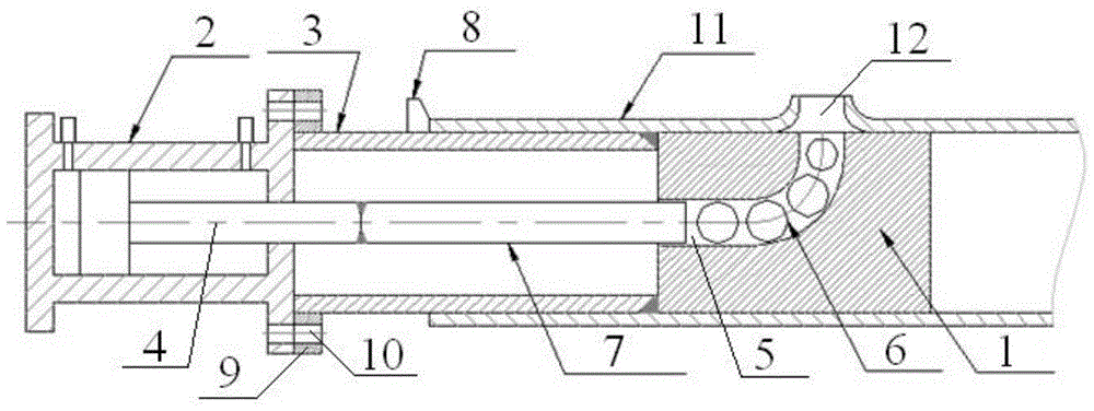
[0015] The key is that the process tooling for small-diameter collecting pipe branch drawing is: the process tooling includes a cylindrical mold 1, an oil cylinder 2, and a guide sleeve 3, one end of the mold 1 is fixedly connected with one end of the guide sleeve 3, and the other end of the guide sleeve 3 One end forms a locking fit with the oil cylinder 2, the diameter of the mold 1 and the outer diameter of the guide sleeve 3 are equal to the inner diameter of the manifold 11, the telescopic rod 4 of the oil cylinder 2, the guide sleeve 3 and the mold 1 are arranged coaxially, and the guide sleeve 3 is The positioning device forms axial positioning with the manifold 11, and one end of the fixed connection between the mold 1 and the guide sleeve 3 is provided with a horizontal ball hole matching the telescopic rod 4, and the side wall of the mold 1 is provided with a vertical ball hole radially, The horizontal ball hole and the vertical ball hole are connected to form a steel...


PUM


Abstract

The invention relates to a process tool for drawing a branch pipe of a small-bore collecting tube. The process tool is characterized in that the diameter of a mold and the outer diameter of a guide sleeve are equal to the inner diameter of the collecting tube; a telescopic rod of an oil cylinder, the guide sleeve and the mold are coaxially arranged, and the guide sleeve and the collecting tube are axially positioned by virtue of a positioning device; a horizontal ball hole matched with the telescopic rod is formed in one end, fixedly connected with the guide sleeve, of the mold, a vertical ball hole is formed in the side wall of the mold along the radial direction and is communicated with the horizontal ball hole to form a steel ball channel, a plurality of steel balls are placed in the steel ball channel, the diameter of the steel ball at the uppermost end in the steel ball channel is minimum, the diameters of the steel balls under the steel ball at the uppermost end gradually increase, and the number of the steel balls is larger than the drawing number of times of a to-be-formed branch pipe. The process tool has the beneficial effects that by adopting a mode of horizontal force application and vertical stress, the straightness and surface quality of the collecting tube can be well guaranteed, the intensive utilization of the thermal energy and the efficient utilization of materials are realized, the automatic control is realized in heating and drawing processes, and the labor intensity of a worker is greatly alleviated.

Description

technical field [0001] The invention belongs to the technical field of manifold production equipment, and relates to a process tooling, in particular to a small-diameter manifold branch pipe drawing process tooling, which is suitable for the drawing of nuclear power super pipe branch pipes, the production of three-way and four-way pipe fittings, pipeline The drawing of the branch pipe on the body. Background technique [0002] The manifold is an important part of the chemical fire tube boiler, which connects the fire surface tube and the drum to realize the efficient circulation of steam and water. The manifold has high thermal parameters, many openings, and complex stress, especially under accident conditions. In order to ensure the safe and efficient operation of the chemical industry, the manifold must have high safety. Therefore, specific requirements are put forward for the design of the manifold, the selection of materials, processing and manufacturing, as well as te...

Claims


Application Information

Patent Timeline
Patent Type & Authority Patents(China)
IPC IPC(8): B21C37/15
Inventor 刘春海许金元
Owner HEBEI HONGRUN NUCLEAR EQUIP SCI & TECH CO LTD
Why Eureka
Try Eureka