An industrial control signal detection system and detection method

A signal detection and signal technology, applied in the field of industrial control signal detection, signal detection system, industrial control signal detection system, can solve the problem of excessive electrical quantity, failure to achieve real-time automatic alarm and monitoring, manual data correlation analysis of historical data Comparing and analyzing problems such as incompetence to achieve the effect of solving information security problems

Active Publication Date: 2018-04-06
SHENZHEN Y& D ELECTRONICS CO LTD
View PDF6 Cites 1 Cited by
  • Summary
  • Abstract
  • Description
  • Claims
  • Application Information

AI Technical Summary

Problems solved by technology

[0003] The current signal maintenance and troubleshooting work mainly relies on the signal microcomputer monitoring system to establish a network for real-time monitoring, but the signal microcomputer monitoring system focuses on result management, and there are obvious deficiencies in process management, and it is impossible to obtain regularity through the collection of monitoring data In addition, although signal microcomputer monitoring equipment has been widely used in the field, many still rely on manual inspection of data changes. In the case of a large amount of data, manual analysis of data correlation and historical data comparison analysis is not competent.
Although almost all kinds of data of signal equipment are collected, the mining and logical analysis of signal data, data sharing and fusion processing are not enough
Except that the signal microcomputer monitoring system has a simple logic to judge that some electrical quantities exceed the standard alarm, other aspects cannot play the role of real-time automatic alarm and monitoring the operation of the signal system

Method used


Image

  • An industrial control signal detection system and detection method
  • An industrial control signal detection system and detection method

Examples


Embodiment Construction

[0027] In order to make the technical problems solved by the present invention, the technical solutions adopted, and the technical effects obtained easy to understand, the specific implementation manners of the present invention will be further described below in conjunction with the specific drawings.

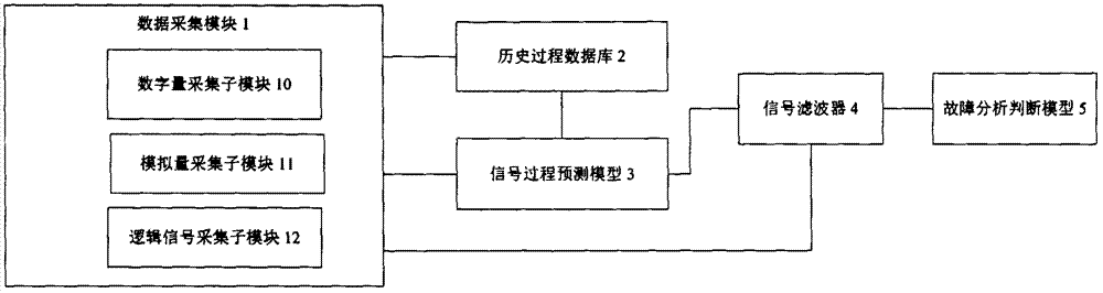
[0028] refer to figure 1 , the present invention provides a kind of industrial control signal detection system, comprising: data acquisition module 1, is used for collecting the real-time state data of the electrical characteristic of equipment; This data acquisition module obtains the real-time state of the electrical characteristic of hardware equipment in the system, mainly includes Voltage, current, frequency, etc. These values ​​can be collected through PLC or DCS system, and only the train control system needs to provide the collection interface. Preferably in the present invention, the data acquisition module 1 includes a digital quantity acquisition submodule 10 , an a...


PUM


Abstract

The invention discloses an industrial control signal detection system and a detection method; the detection system comprises a data collecting module which collects real-time status data of equipment electrical features, and a historical process database which is connected with the data collecting module and used for storing the real-time status data collected by the data collecting module; the detection system further comprises a signal process predicating model which is connected with the historical process database and establishes correspondence between signal input and output in the electrical features based on the data inside the historical process database; the signal process predicating model obtains a predicated output signal based on the real-time input signal collected by the data collecting module, and sends the predicated output signal to a signal filter; the signal filter receivers the predicated output signal from the signal process predicating model and the real-time output signal collected by the data collecting module, and compares the signals, if the feature of the corresponding real-time output signal accords with the feature of the predicated output signal, then the real-time output signal is judged to be an effective executable signal; otherwise, the real-time output signal is judged to be a negative non-executable signal.

Description

technical field [0001] The invention belongs to the field of information security of industrial control systems, specifically, it relates to a detection system for industrial control signals, more precisely, it relates to a detection system for signals of trains such as high-speed railways and subways; the invention also relates to an industrial control signal detection system detection method. Background technique [0002] The train control system is the integration of various signal equipment and subsystems and their auxiliary equipment. System integration is one of the key technologies of high-speed rail signaling, which is directly related to the safety of the system. Functional Requirements Specification (FRS), System Requirements Specification (SRS) and System Interface Specification (FIS) of train control system are the main basis for system integration. The current train control system integration focuses on the interface technology between different equipment or s...

Claims


Application Information

Patent Timeline
Patent Type & Authority Patents(China)
IPC IPC(8): G05B23/02
CPCG05B23/0213
Inventor 戚建淮方方赵海阳曾旭东
Owner SHENZHEN Y& D ELECTRONICS CO LTD
Why Eureka
Try Eureka