Laser pulse energy stabilizing device and method

A laser pulse and stabilizing device technology, applied in the laser field, can solve problems such as limited linear amplification area of ​​high-voltage amplifier circuit, time waveform distortion, and influence on energy control accuracy, so as to achieve the effect of benefiting energy, fast response speed, and reducing energy fluctuations

Inactive Publication Date: 2015-05-13
LASER FUSION RES CENT CHINA ACAD OF ENG PHYSICS
View PDF7 Cites 2 Cited by
  • Summary
  • Abstract
  • Description
  • Claims
  • Application Information

AI Technical Summary

Problems solved by technology

It uses a fast photoelectric sampling gate to obtain laser pulse sampling signals, outputs a low-voltage electrical pulse that is linearly proportional to the laser pulse amplitude, and then amplifies it into a high-voltage electrical pulse through a linear electrical pulse high-voltage amplifier and loads it on the electrode of the Pockels cell electro-optic switch. The linear amplification area of ​​the hi

Method used


Image

  • Laser pulse energy stabilizing device and method
  • Laser pulse energy stabilizing device and method
  • Laser pulse energy stabilizing device and method

Examples


Embodiment 1

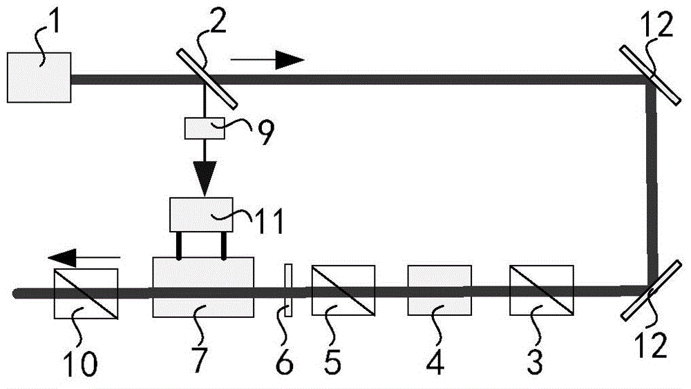
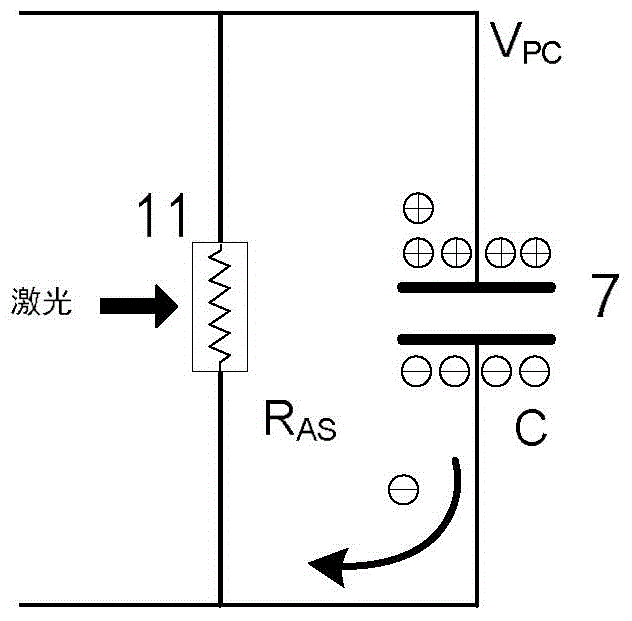
[0032] Such as figure 1 As shown, a laser pulse energy stabilization device includes a main optical path and a sampling optical path, and the main optical path includes a seed light source 1, an optical path transmission delay device 12, a polarizer 3, a Faraday magnetic rotator 4, and a polarizer two arranged in sequence 5. 1 / 4 wave phase retarder 6, Pockels cell electro-optic switch 7, polarizer three 10, the transmission path of the laser light generated by the seed light source 1 in the main optical path is: optical path transmission delay device 12, polarizer one 3 , Faraday magnetic rotator 4, polarizer two 5, 1 / 4 wave phase retarder 6, Pockels cell electro-optic switch 7, polarizer three 10, described Pockels cell electro-optic switch 7 is an electro-optic switch of diduterium potassium phosphate , one-way work, 1 / 2 wave voltage is 7kV, equivalent capacitance C is 14pF, pre-applied voltage V 0 is 7kV.

[0033] Such as figure 1As shown, the sampling optical path inclu...

Embodiment 2

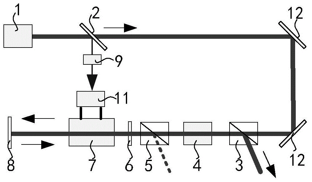
[0040] Such as figure 2 As shown, a laser pulse energy stabilization device includes a main optical path and a sampling optical path, and the main optical path includes a seed light source 1, an optical path transmission delay device 12, a polarizer 3, a Faraday magnetic rotator 4, and a polarizer two arranged in sequence 5. 1 / 4 wave phase retarder 6, Pockels cell electro-optic switch 7, total reflection mirror 8, the transmission path of the laser light generated by the seed light source 1 in the main optical path is: optical path transmission delay device 12, polarizer-3 , Faraday magnetic rotator 4, polarizer 2 5, 1 / 4 wave phase retarder 6, Pockels cell electro-optic switch 7, total reflection mirror 8, Pockels cell electro-optic switch 7, 1 / 4 wave phase retarder 6 , polarizer two 5, Faraday magnetic rotator 4, polarizer one 3, the Pockels cell electro-optic switch 7 is an electro-optic switch of diduterium potassium phosphate, two-way work, 1 / 4 wave voltage is 3.5kV, pre-...


PUM


Abstract

The invention discloses a laser pulse energy stabilizing device and method and belongs to the technical field of lasers. The device is divided into a main optical path and a sampling optical path. The main optical path is provided with a Pockels cell electro-optical switch. The sampling optical path is provided with a photoconductive switch. The method includes the steps of first detecting laser pulse energy fluctuation and then quickly discharging driving voltage applied to both electrodes of the Pockels cell electro-optical switch through the photoconductive switch. The laser pulse energy stabilizing device and method achieves energy stability control of the same laser pulse through the laser pulse energy fluctuation, has a self-stabilizing characteristic and does not cause laser pulse time waveform distortion.

Description

technical field [0001] The invention relates to the field of laser technology, in particular to a laser pulse energy stabilization device and an energy stabilization method thereof. Background technique [0002] High-power pulsed laser systems require that the laser pulses generated by the seed light source system not only have stable energy, but also have a specific time waveform distribution. The traditional method of stabilizing laser pulse energy is to measure the laser pulse energy and compare it with the target energy, and adjust the controller or driving power upstream of the optical path according to the difference between the test energy and the target energy. This method can only correct the next laser pulse according to the energy fluctuation of the current pulse. If the fluctuation law and scale of the next laser pulse are inconsistent with the fluctuation law and scale of the current measured laser pulse, the stabilization effect will be compromised or even chan...

Claims


Application Information

Patent Timeline
IPC IPC(8): H01S3/13
Inventor 谢旭东唐军陈骥朱启华党钊唐菱高松胡东霞郑万国王正辉王超陈远斌汪凌芳陈林王方刘勇刘建国卢振华
Owner LASER FUSION RES CENT CHINA ACAD OF ENG PHYSICS
Why Eureka
Try Eureka