
Reciprocating Powder Spreader for Selective Laser Melting

A powder spreading device and laser melting technology, which is applied in the field of powder laser sintering additive manufacturing, can solve the problems of inability to ensure the uniformity of powder spreading, increase the overall structure space, and inability to perform circulating powder supply, so as to achieve a compact structure and improve work efficiency. Efficiency, the effect of reducing the waste of time

Active Publication Date: 2016-10-05
CHONGQING UNIV
View PDF7 Cites 0 Cited by
  • Summary
  • Abstract
  • Description
  • Claims
  • Application Information

AI Technical Summary

Problems solved by technology

Its disadvantages are: adopting the bottom powder supply method, the additional powder supply chamber increases the overall structural space, the powder amount needs to be added at one time, and the powder supply cannot be carried out in a cycle; the scraper needs to move back and forth to complete a powder coating, resulting in an empty stroke , a waste of time; not suitable for the processing of large parts; for powder spreading on large platforms, the uniformity of powder spreading before and after the powder spreading process cannot be guaranteed; and the structure is complex and the control is complicated

Method used


Image

  • Reciprocating Powder Spreader for Selective Laser Melting
  • Reciprocating Powder Spreader for Selective Laser Melting
  • Reciprocating Powder Spreader for Selective Laser Melting

Examples


Embodiment Construction

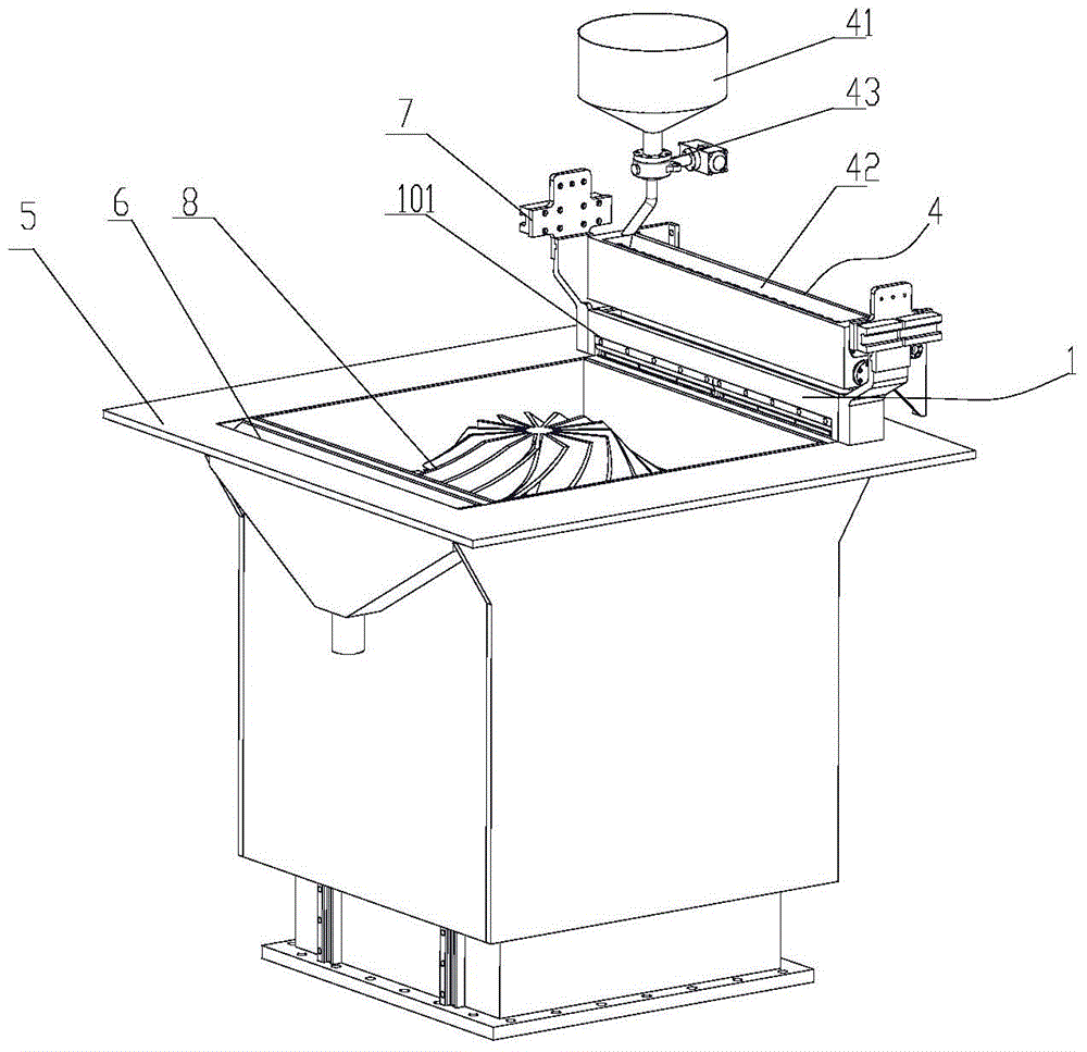
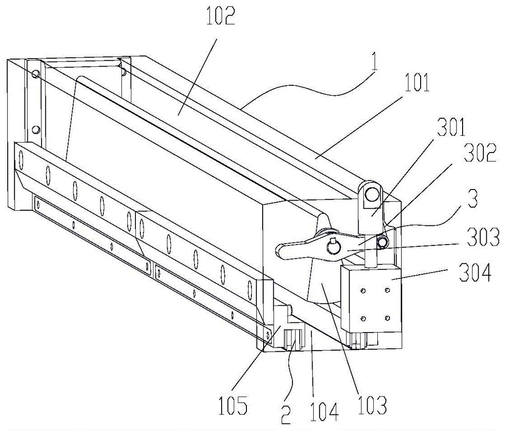
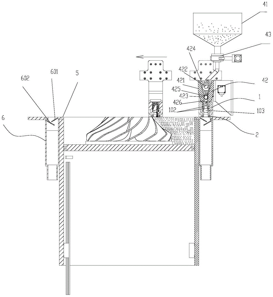
[0027] figure 1 It is a schematic diagram of the overall structure of the reciprocating powder spreading device for selective laser melting of the present invention; figure 2 It is a structural schematic diagram of the powder spreading mechanism of the reciprocating powder spreading device used for selective laser melting in the present invention; image 3 It is a working diagram of the structure of the powder spreading mechanism of the reciprocating powder spreading device for selective laser melting of the present invention; Figure 4 It is a structural schematic diagram of the powder scraping assembly of the reciprocating powder spreading device for selective laser melting of the present invention; Figure 5 It is a schematic diagram of the soft blade splicing structure of the reciprocating powder spreading device for selective laser melting of the present invention; Figure 6 It is a structural schematic diagram of the driving mechanism of the powder spreading mechanism...


PUM


Abstract

The invention discloses a reciprocating powder laying device for selective laser melting. The reciprocating powder laying device comprises a powder laying mechanism which can lay powder in a reciprocating manner. The powder laying mechanism comprises powder laying box which can transversely move in a reciprocating manner and a partition, wherein the partition is disposed in the powder laying box, powder laying cavities are formed on two transverse sides of the partition, the lower end of the partition communicates the powder laying cavities and powder outlets below the powder laying box in an openable manner. When the powder laying box moves, the partition can transversely swing to allow the rear powder laying cavity in the advancing direction of the powder laying box to be communicated with the powder outlets. The reciprocating powder laying device has the advantages that twice powder laying is performed by one reciprocation, no idle running exists in the middle, time waste is reduced greatly, work efficiency is increased, pausing during powder laying can be avoided, and the device is suitable for large parts; an upper power feeding manner is used, compactness in structure is achieved, overall structural space is reduced greatly, circulating power feeding can be achieved, sufficient powder can be fed at one step, and powder can be saved effectively.

Description

technical field [0001] The invention relates to the field of powder laser sintering additive manufacturing, in particular to a reciprocating powder spreading device for selective laser melting. Background technique [0002] Powder spreading is an important part of selective laser melting. The powder spreading effect affects the compactness of the powder, which in turn directly affects the molding quality of the part. During the powder spreading process, the compactness of the powder is related to factors such as the flow of the powder and the pressure on the lower layer of powder. The existing powder spreading method is composed of a powder supply bin, a forming bin, a powder collecting bin, and a scraper, etc., and is realized by moving the powder supply bin upward to push out excess powder, and the scraper moves and spreads in the forming bin. Usually an additional feed bin is moved up to provide the powder. Its disadvantages are: adopting the bottom powder supply method...

Claims


Application Information

Patent Timeline
Patent Type & Authority Patents(China)
IPC IPC(8): B22F3/105
Inventor 张正文刘飞傅广毛忠发王海亮张鹏
Owner CHONGQING UNIV
Learn More