Steel rail grinding machine

A grinding machine and grinding mechanism technology, which is applied to the parts of grinding machine tools, grinding machines, grinding/polishing equipment, etc., can solve problems such as inaccurate flaw detection results, and achieve the effects of ensuring health and improving grinding speed and precision

Inactive Publication Date: 2015-05-20
戚恒
View PDF8 Cites 13 Cited by
  • Summary
  • Abstract
  • Description
  • Claims
  • Application Information

AI Technical Summary

Problems solved by technology

[0006] During the operation process, the wave of welding bars in the triangular area of ​​the rail bottom, the welding bars of the rail bottom pla

Method used


Image

  • Steel rail grinding machine
  • Steel rail grinding machine
  • Steel rail grinding machine

Examples


Embodiment 1

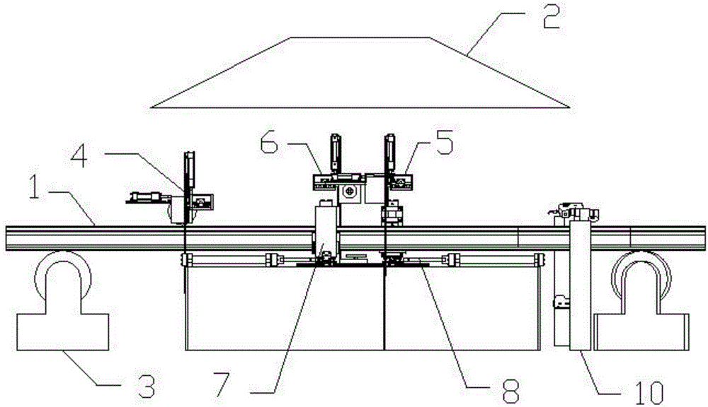
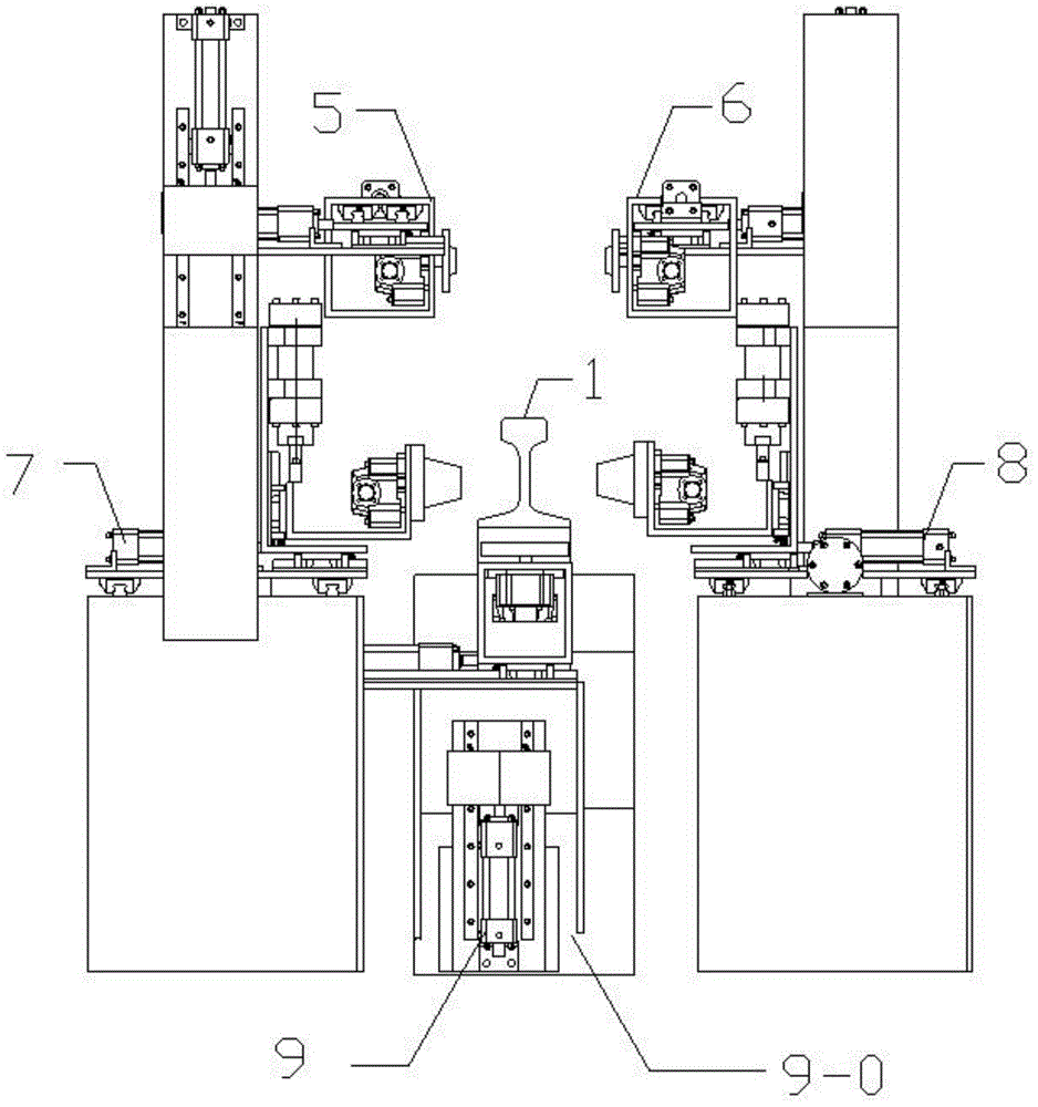
[0061] Example 1: A rail grinding machine, its structure reference Figure 2-4 Shown include:

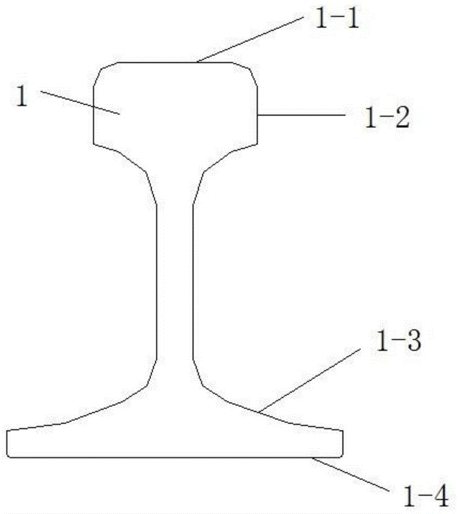
[0062] Rail top surface grinding mechanism 4, rail head side grinding mechanism, rail triangle grinding mechanism, rail bottom grinding mechanism 9, running line drum 3 and dust cover 2, rail 1 is caught by the rail while sliding on the running line drum 3 The top surface grinding mechanism 4, the rail head grinding mechanism, the rail triangle grinding mechanism and the rail bottom grinding mechanism 9 are ground, and the dust generated during the grinding process is sucked away by the dust hood 2;

[0063] The traveling line roller 3 includes a support 3-1, and a roller 3-2 is installed on the support 3-1.

[0064] reference Figure 7 As shown, the rail bottom grinding mechanism 9 includes a central base 9-0, a backing plate 9-1 is fixedly connected to the central base 9-0, and a Z-direction oil cylinder 9-2 and Z-direction guide rail 9-3, Z-direction oil cylinder 9-2 drives Z-direction...


PUM


Abstract

The invention relates to a steel rail grinding machine which comprises a steel rail top surface grinding mechanism, a steel rail head side surface grinding mechanism, a steel rail triangular region grinding mechanism, a steel rail bottom grinding mechanism and a travelling line roller, wherein a steel rail is ground by the steel rail top surface grinding mechanism, the steel rail head grinding mechanism, the steel rail triangular region grinding mechanism and the steel rail bottom grinding mechanism in a process of sliding on the travelling line roller, wherein the steel rail bottom grinding mechanism comprises a center base, a base plate is fixedly connected onto the center base, a Z-direction oil cylinder and a Z-direction guide rail are arranged on the base plate, the Z-direction oil cylinder drives a Z-direction sliding base to reciprocate on the Z-direction guide rail; a Y-direction oil cylinder and a Y-direction guide rail are fixedly arranged on the top surface of the Z-direction sliding base, the Y-direction oil cylinder drives the Y-direction sliding base to reciprocate on the Y-direction guide rail; a hydraulic motor is vertically arranged inside the Y-direction sliding base, and an output shaft of the hydraulic motor is fixedly connected with a rail bottom grinding head.

Description

Technical field [0001] The invention relates to the field of railway equipment, in particular to a rail grinding machine. Background technique [0002] After the rail is welded, the rail welding seam must be milled first, and there are tool marks at the bottom of the rail after milling. After milling is completed, the rail needs to be polished to eliminate tool marks and residual weld margins at the bottom of the rail, and to improve the surface flatness of the rail. [0003] figure 1 It is an explanatory drawing of each area of ​​the rail. [0004] At present, the rail grinding method is mostly manual hand-held grinder for grinding. During the grinding process, the grinding amount is controlled by manual experience, resulting in low grinding accuracy. At the same time, a large amount of dust will be generated during the grinding process. Although the staff wears protective devices, the harm to health is still great. [0005] After the rail is polished, flaw detection is required. ...

Claims


Application Information

Patent Timeline
IPC IPC(8): B24B27/00B24B19/00B24B41/04B24B49/12B24B55/06
CPCB24B19/004B24B27/0076B24B41/04B24B49/12B24B55/06
Inventor 戚恒
Owner 戚恒
Why Eureka
Try Eureka