
Grinding head capable of controlling pressure distribution

A pressure distribution and grinding head technology, applied in grinding heads, manufacturing tools, machine tools with surface polishing, etc., can solve the problem of uncontrollable pressure distribution of grinding heads, and achieve the effect of improving the influence of edge effects.

Inactive Publication Date: 2015-05-20
CHANGCHUN INST OF OPTICS FINE MECHANICS & PHYSICS CHINESE ACAD OF SCI
View PDF8 Cites 17 Cited by
  • Summary
  • Abstract
  • Description
  • Claims
  • Application Information

AI Technical Summary

Problems solved by technology

[0004] The purpose of the present invention is to provide a grinding head with controllable pressure distribution, so as to solve the technical problem that the pressure distribution of the grinding head in the prior art is uncontrollable

Method used


Image

  • Grinding head capable of controlling pressure distribution

Examples


specific Embodiment approach 2

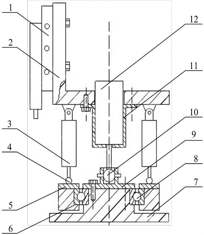
[0020] The difference between this embodiment and Embodiment 1 is that the three groups of cylinders 3 are evenly distributed on the bottom of the support 2, and the three groups of cylinders 3 are respectively equipped with pressure regulating valves and reversing valves, which can control the pressure distribution to change in various directions. One end of the cylinder 3 is connected on the support 2 by a hinge, and the direction of the axis of rotation of the hinge will be perpendicular to the connecting line between the motor 12 and the axis of the hinge, and the other end of the cylinder 3 is connected with the upper cover plate 5 of the bearing outer ring by a ball hinge. The diameter of the ball head 10 should be slightly smaller than the diameter of the cylinder hole, so that the ball head 10 can swing freely in the cylinder hole without a large gap, and the cylindrical pins at both ends of the ball head 10 are stuck in the grooves on both sides of the cylinder to ensur...


PUM


Abstract

The invention discloses a grinding head capable of controlling pressure distribution and belongs to the technical field of optics cold processing, and a technical problem of pressure distribution of a grinding head in the prior art is solved. The grinding head capable of controlling the pressure distribution comprises a sliding table air cylinder, a rack, a motor, air cylinders, a bearing, an upper cover plate of a bearing inner ring, an upper cover plate of a bearing outer ring, and a grinding head body, wherein the sliding table air cylinder is in threaded connection with the rack; the multiple air cylinders are uniformly distributed on the rack along the periphery of the rack, and the air cylinders are hinged to the rack; the air cylinders are connected with the upper cover plate of the bearing outer ring through spherical hinges; the motor is connected with a motor seat through a thread, and the motor seat is connected with the rack through a thread; the upper cover plate of the bearing inner ring is connected with the grinding head body through screws and tightly presses the bearing inner ring; an output shaft of the motor is fixedly connected with a ball head, the upper half portion of the upper cover plate of the bearing inner ring is a cylinder with a hole in the center, vertical through grooves are symmetrically formed in the side surfaces of the cylinder, and cylindrical pins on the two sides of the ball head are clamped into the through grooves.

Description

technical field [0001] The invention belongs to the technical field of optical cold processing, and in particular relates to a grinding head capable of controlling pressure distribution. Background technique [0002] The polishing process is the last link in the optical cold processing. In the polishing process, the polishing mold is usually attached to the surface of the workpiece to form a stable polishing pressure. In this way, the removal of the polishing mold can be calculated and controlled by a simple formula. However, at the edge position, since a part of the grinding head leaves the workpiece surface, the pressure on the rest of the grinding head that is in contact with the workpiece changes greatly, and the removal amount is difficult to control, eventually forming an edge effect. In the current polishing process, the edge effect has a great influence on the surface shape of the component, but it is almost inevitable. The fundamental reason is that the pressure und...

Claims


Application Information

Patent Timeline
Patent Type & Authority Applications(China)
IPC IPC(8): B24B41/04B24B29/00
CPCB24B29/00B24B41/002B24B41/04
Inventor 王绍志刘健隋永新杨怀江
Owner CHANGCHUN INST OF OPTICS FINE MECHANICS & PHYSICS CHINESE ACAD OF SCI
Learn More